The system uses AT89C52 microcontroller as the controller, the entire circuit is mainly controlled by the microcontroller and its interface circuit, drive display circuit, power circuit and other components. In order to simplify the display circuit and reduce the cost, the system does not add font memory in the microcontroller. On the PC, the Chinese character and character display information are edited and converted into corresponding dot matrix display data, which are then sent to the SCM for storage and display processing through the serial port (using the RS-232 communication standard). Figure 1 shows the hardware system schematic.
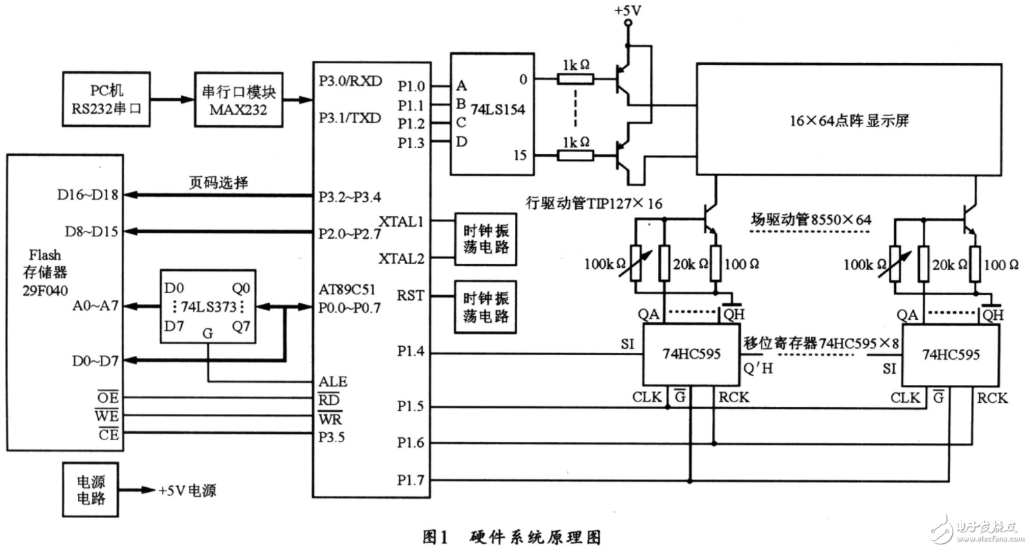
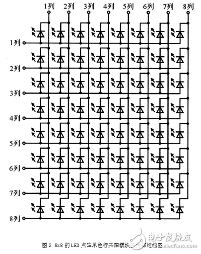
Figure 2 shows the internal structure of an 8x8 LED dot-matrix monochrome line common-mode module. The single-point operating voltage Uf is 1.8 V and the forward current IF is 8~10 mA. When a row line is high and one column line is low, the intersection of its ranks is lit; when one of the column lines is high, the intersection of its ranks is dark; when a row is low At the level, regardless of the column line, the point corresponding to this line is all dark.
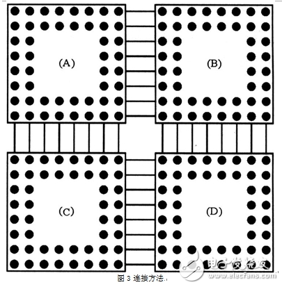
Using four 8x8 dot matrix displays to form a 16x16 dot matrix display, the connection method is shown in Figure 3. In the figure, connect the 8 columns of (A) and (B), and the 8 columns of (C) and (D), respectively, and connect the 8 rows, (B) and (D) of (A) and (C). The 8 lines correspond to each other. A 16x16 dot matrix display can be formed with 16 rows (16 LEDs per row) and 16 columns (each column also has 16 LEDs). These 256 points can be referred to as one page, so that the characters are displayed. As long as the corresponding light and off in a page can be controlled.
The design of the LED display driver circuit should be coordinated with the control system used. Drivers are usually divided into dynamic scan and static latch drivers. This article takes the design of a dynamic scan drive circuit as an example to analyze. The dynamic scan driving mode means that the 16 rows of light emitting diodes on the display screen share a set of column driver registers, and then the time for driving each row of LEDs accounts for 1/16 of the total time by time-sharing the row driving tubes. As long as the refresh rate of each line is greater than 50 Hz, people can see a complete text or picture using the persistence effect of human eyes.
The 74HC138 works on high-performance memory decoding or data transmission systems that require short propagation delays. In high-performance memory systems, using such a decoder can increase the efficiency of the decoding system. When the fast enable circuit is used in a high speed memory, the delay time of the decoder and the power generation time of the memory are usually less than the typical access time of the memory, which means that the system is translated by the Schottky clamp. The effective system delay caused by the encoder is negligible. The HC138 outputs a low level output from the eight outputs in accordance with the three-bit binary input code and the enable input conditions.
AT89S52 microcontroller has four I / O ports (P0, P1, P2, P3), each I / O port has 8, if you are using parallel output, obviously can not meet the requirements, therefore, the design of the line scan drive used Parallel output, while the field scan driver uses serial output.
Line scan drive
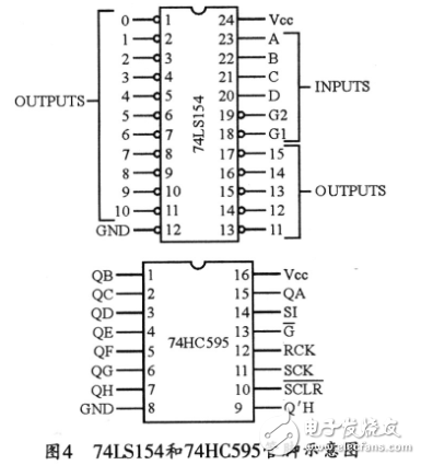
Since the 16x64 dot matrix display has 16 lines, in order to make full use of the interface of the single chip microcomputer, a 4-16 line decoder 74LS154 is added to this circuit. Its input is a hexadecimal code, and the decoded output is a low state scan signal. The pin diagram is shown in Figure 4. Connect the G1 and G2 pins of the 74LS154 to ground and use the A, B, C, and D pins as inputs. It will form 16 different input states, respectively 0000 ~ 1111, and then make each state only control one output, that is there will be 16 outputs. If all of the 64 points are lit, the current through 74LS154 will reach 640 mA. Actually, the 74LS154 decoder does not provide enough current to drive 64 LEDs at the same time. Therefore, it should output at 74LS154 each. A triode is used to amplify the current signal between each terminal corresponding to the 16x64 dot matrix display. The Darlington transistor TIP127 is used in this paper. In this way, when a certain output pin of 74LS154 is low, the emitter of the corresponding transistor is high, so that the corresponding line of the dot matrix display is also high.
Column scan drive
The design of the system field scan drive circuit can be used as a data latch in a serial integrated circuit 74HC595. The 74HC595 is an 8-bit serial input 3-state parallel output shift register whose pins are shown in Figure 4, where SI is the serial data input, RCK is the input clock to the storage register, and SCK is the shift register. Input clock, Q'H is the output of serial data, G is the output enable control of the input data, and QA ~ QH is the parallel output of serial data. Data input from the SI port can be input to the 74HC595 with the rising edge of the SCK pin of the shift register. The input data is latched in the 74HC595 under the rising edge of the RCK pin so that when G is low, the data can be output in parallel. In order to avoid mutual interference with PC serial port input data, analog serial ports P1.4~P1.7 can also be used to output serial data, shift clock SCK, storage signal RCK, and parallel output enable signal G, respectively.
In order to eliminate the fluctuation of the power supply voltage and the pressure drop of the line scanning tube (the number of points lighted in the first line will cause changes in the pressure drop of the tube, thereby affecting the current through the LED tube) to influence the brightness of the LED display, Column constant current drive circuit can be used, optional transistor 8550 and external components constitute the column constant current drive circuit, and by adjusting the 100 kΩ adjustable resistor triode is in a state of amplification, while the collector current is adjusted to 10 mA, so that the light The current through the LED does not change during the corresponding dot matrix.
Scanning shows the working process
When eight 74HC595s are cascaded, one shift clock SCK and data latch signal RCK can be shared. In this way, when the first line of data to be displayed goes through 8x8=64 SCK clocks, it can all be shifted into the 74HC595. At this time, a data latch signal RCK will be generated to latch the data in the 74HC595 and enable signals. Under the action of G, the serial data is output in parallel, so that the field driving tube corresponding to each output bit is in an amplified or cut-off state; at the same time, the signal generated by the line scan control circuit makes the first row of scanning tubes conduct, which is equivalent to the first The positive ends of the row LEDs are all connected high. Obviously, the first row of LED tubes depends on the latch signal in the 74HC595; in addition, when the first row of LED tubes is lit, the second row is moved in the 74HC595. The data to be displayed is then latched, while the row scanning control circuit closes the first row of scan tubes and turns on the second row, causing the second row of LED tubes to light up, and so on, when the 16th row scans. Go back to the first line afterwards, so that as long as the scanning speed is high enough, you can form a complete text or image.
Software design flow chart
code
#include"reg52.h"
Char tab[32]={
0x00, 0x00, 0x10, 0x00, 0x90, 0x3F, 0x90, 0x10, 0xFF, 0x10, 0x90, 0x10, 0x90, 0xBF, 0x10, 0x40,
0x00, 0x30, 0xFE, 0x0F, 0x22, 0x02, 0x22, 0x42, 0x22, 0x82, 0xFE, 0x7F, 0x00, 0x00, 0x00, 0x00};
Char tab1[32]={
0x10, 0x04, 0x10, 0x03, 0xD0, 0x00, 0xFF, 0xFF, 0x90, 0x00, 0x10, 0x11, 0x00, 0x08, 0x10, 0x04,
0x10, 0x03, 0xD0, 0x00, 0xFF, 0xFF, 0xD0, 0x00, 0x10, 0x03, 0x10, 0x04, 0x10, 0x08, 0x00, 0x00};
Char tab2[32]={
0x10, 0x04, 0x60, 0x04, 0x02, 0x7C, 0x0C, 0x03, 0xC0, 0x20, 0x04, 0x20, 0x04, 0x20, 0x04, 0x20,
0x04, 0x20, 0xFC, 0x3F, 0x04, 0x20, 0x04, 0x20, 0x04, 0x20, 0x04, 0x20, 0x00, 0x20, 0x00, 0x00};
Void delay(int z)
{
Int x,y;
For(x=z;x"0;x--)
For(y=10;y"0;y--);
}
Void main(void)
{
Int i,j;
While(1)
{
For(i=200;i"0;i--)
{
P3 = 0xf0;
P0 = tab[0];
P2 = tab[1];
Delay(1);
P3 = 0xf1;
P0 = tab[2];
P2 = tab[3];
Delay(1);
P3 = 0xf2;
P0 = tab[4];
P2 = tab[5];
Delay(1);
P3 = 0xf3;
P0 = tab[6];
P2 = tab[7];
Delay(1);
P3 = 0xf4;
P0 = tab[8];
P2 = tab[9];
Delay(1);
P3 = 0xf5;
P0 = tab[10];
P2 = tab[11];
Delay(1);
P3 = 0xf6;
P0 = tab[12];
P2 = tab[13];
Delay(1);
P3 = 0xf7;
P0 = tab[14];
P2 = tab[15];
Delay(1);
P3 = 0xf8;
P0 = tab[16];
P2 = tab[17];
Delay(1);
P3 = 0xf9;
P0 = tab[18];
P2 = tab[19];
Delay(1);
P3 = 0xfa;
P0 = tab[20];
P2 = tab[21];
Delay(1);
P3 = 0xfb;
P0 = tab[22];
P2 = tab[23];
Delay(1);
P3 = 0xfc;
P0 = tab[24];
P2 = tab[25];
Delay(1);
P3 = 0xfd;
P0 = tab[26];
P2 = tab[27];
Delay(1);
P3 = 0xfe;
P0 = tab[28];
P2 = tab[29];
Delay(1);
P3 = 0xff;
P0 = tab[30];
P2 = tab[31];
}
For(j=200;j"0;j--)
{
P3 = 0xf0;
P0 = tab1[0];
P2 = tab1[1];
Delay(1);
P3 = 0xf1;
P0 = tab1[2];
P2 = tab1[3];
Delay(1);
P3 = 0xf2;
P0 = tab1[4];
P2 = tab1[5];
Delay(1);
P3 = 0xf3;
P0 = tab1[6];
P2 = tab1[7];
Delay(1);
P3 = 0xf4;
P0 = tab1[8];
P2 = tab1[9];
Delay(1);
P3 = 0xf5;
P0 = tab1[10];
P2 = tab1[11];
Delay(1);
P3 = 0xf6;
P0 = tab1[12];
P2 = tab1[13];
Delay(1);
P3 = 0xf7;
P0 = tab1[14];
P2 = tab1[15];
Delay(1);
P3 = 0xf8;
P0 = tab1[16];
P2 = tab1[17];
Delay(1);
P3 = 0xf9;
P0 = tab1[18];
P2 = tab1[19];
Delay(1);
P3 = 0xfa;
P0 = tab1[20];
P2 = tab1[21];
Delay(1);
P3 = 0xfb;
P0 = tab1[22];
P2 = tab1[23];
Delay(1);
P3 = 0xfc;
P0 = tab1[24];
P2 = tab1[25];
Delay(1);
P3 = 0xfd;
P0 = tab1[26];
P2 = tab1[27];
Delay(1);
P3 = 0xfe;
P0 = tab1[28];
P2 = tab1[29];
Delay(1);
P3 = 0xff;
P0 = tab1[30];
P2 = tab1[31];
}
For(j=200;j"0;j--)
{
P3 = 0xf0;
P0 = tab2[0];
P2 = tab2[1];
Delay(1);
P3 = 0xf1;
P0 = tab2[2];
P2 = tab2[3];
Delay(1);
P3 = 0xf2;
P0 = tab2[4];
P2 = tab2[5];
Delay(1);
P3 = 0xf3;
P0 = tab2[6];
P2 = tab2[7];
Delay(1);
P3 = 0xf4;
P0 = tab2[8];
P2 = tab2[9];
Delay(1);
P3 = 0xf5;
P0 = tab2[10];
P2 = tab2[11];
Delay(1);
P3 = 0xf6;
P0 = tab2[12];
P2 = tab2[13];
Delay(1);
P3 = 0xf7;
P0 = tab2[14];
P2 = tab2[15];
Delay(1);
P3 = 0xf8;
P0 = tab2[16];
P2 = tab2[17];
Delay(1);
P3 = 0xf9;
P0 = tab2[18];
P2 = tab2[19];
Delay(1);
P3 = 0xfa;
P0 = tab2[20];
P2 = tab2[21];
Delay(1);
P3 = 0xfb;
P0 = tab2[22];
P2 = tab2[23];
Delay(1);
P3 = 0xfc;
P0 = tab2[24];
P2 = tab2[25];
Delay(1);
P3 = 0xfd;
P0 = tab2[26];
P2 = tab2[27];
Delay(1);
P3 = 0xfe;
P0 = tab2[28];
P2 = tab2[29];
Delay(1);
P3 = 0xff;
P0 = tab2[30];
P2 = tab2[31];
}
}
}
Gear Sensor has been widely used in the automotive and industrial field, which is important to the measurement of velocity, angel, angular velocity, direction of rotation.
Gear Sensor,Custom Gear Sensor,Gear Sensor 3 Pins,Good Gear Sensor
Yuheng Optics Co., Ltd.(Changchun) , https://www.yhenoptics.com