Design of Engine Calibration and Diagnosis System Based on ASAP Standard
Abstract: A hierarchical and modular concept is used to design a calibration diagnostic system based on the ASAP standard. The software watchdog technology is used in the host computer to solve the problem of rapid fault location between the calibration tool and the engine electronic control unit. The host computer automatically saves the calibration data during the fault, and automatically issues the calibration data after the fault is repaired, thereby preventing the loss of the calibration data and avoiding the repetitive calibration work. And can read the database file of the foreign calibration system, its reliability and versatility are further enhanced.
Keywords: calibration system; engine; diagnosis; ASAP standard; software watchdog
Design of engine calibraTIon diagnosis system based on ASAP standards
Li Yin-guo Cao Geng-yan Cen Ming (Chongqing University of Posts and Telcoms, Chongqing China 400065)
Abstract: A calibraTIon and diagnosis system based on ASAP standards was designed using layer and modularizaTIon idea. The malfuncTIon between host computer and ECU was positioned quickly
through the software watchdog technology in the host computer. and the calibrated datas were autosaved into the Caliration tool. After the malfunction was repaired, these datas were sent to the RAM of ECU. So this can avoid the datas'losing and the calibration's repetition. Also it can read foreign calibration software's description file.it's reliability and universality was strengthened.
Key words: calibration system, Engine, diagnosis, ASAP standards, Software Watchdog
Introduction The engine electronic control unit (ECU) is the core of the engine control system for vehicles. It can provide the best air-fuel ratio and ignition time according to the operation of the engine, so as to optimize the power, economy and exhaust emissions of the engine. [1]. Therefore, it is very important to develop a calibration tool that is reliable, convenient, and flexible. It can shorten the development cycle of ECU,
Reduce the workload of matching experiments, reduce development costs, and help calibrators get the best calibration parameters in a short time.
Judging from the available data, the calibration system designed in China generally has the functions of calibration, monitoring and diagnosis. However, its diagnostic function only displays the fault information provided by the ECU on the host computer. There is no introduction on the rapid fault location and repair between the host computer and the ECU. In addition to the online calibration, real-time monitoring and the ability to read the fault information in the ECU, the calibration diagnostic system designed in this paper uses software to watch the calibration host computer. Dog technology realizes the rapid fault location between the host computer and the ECU, and has the functions of automatic saving, loading, and reading back comparison data. Enhance the reliability and flexibility of the calibration system.
1 ASAP standard architecture
ASAP (Arbeitskreis zur Standardisierung von Applikationssystemen) refers to the organization for standardization of application systems. This international standard is proposed in order to make the tools and methods used in the development of automotive electronic products compatible and interchangeable [2]. In order to realize the measurement, calibration and diagnosis of the application system, the ASAP working group according to MCD (Measurement,
Calibration and Diagnostics) model divides the standard into three sub-standards of ASAP1, ASAP2 and ASAP3.
The ASAP1 standard provides an interface between the application system and the control equipment; the ASAP2 standard provides a standardized description of various internal parameters, external interface information, and communication methods of the ECU. The ASAP description file generated according to this standard is for all types of control equipment Data exchange platform; ASAP3 standard provides a unified interface between the automatic system (or user) and the MCD system. The user only needs to call the interface function provided by the MCD system to complete the functions of measurement, calibration and diagnosis.
2 The overall design of the calibration system uses a PC as the host computer, which is connected to the engine ECU through a USB-CAN communication card to achieve the calibration and
Operations such as monitoring and diagnosis. The communication and data exchange platform between the host computer and the ECU is implemented by the CSAP protocol in the ASAP standard and the ASAP description file (.A2L file) generated by the ASAP2 standard. The calibration software of the host computer is designed with layered and modular ideas, including data layer, presentation layer and communication layer (see Figure 1). The data layer includes the initialization subsystem and the data management subsystem. The initialization subsystem mainly completes the CAN communication module and data initialization and other operations. The data management subsystem mainly completes the operations of data storage, loading, playback and A2L database management; the presentation layer includes the calibration monitoring subsystem and the diagnosis subsystem, which mainly completes the calibration, monitoring and diagnosis of the engine ECU; The communication layer is mainly to complete the communication operation between the host computer and the ECU.
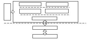
Figure 1 The overall frame diagram of the calibration diagnostic system The A2l database generated by the ASAP editor is the data exchange platform for the entire calibration system. Therefore, at the beginning of the system operation, first import the A2L file, and then call the interface library function provided by the CAN communication module to complete the CAN communication module Initialization and other operations,
After the connection is established, multiple ECUs can be calibrated and monitored. Fault diagnosis (ECU fault information upload display and fault diagnosis of the calibration system) runs through the entire process of calibration and monitoring (see Figure 2).
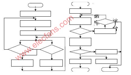
Fig. 2 Main flow chart of upper computer Fig. 3 Initialization flow chart of calibration data
2.1 Design of the initialization subsystem In this subsystem, the initialization of the USB-CAN module, the initialization of the calibration parameters and the initialization configuration of the DAQ parameters are included.
The host computer performs the following initialization operations in turn by calling the relevant interface library functions of the CAN communication module: opening the CAN communication module, selecting the CAN port connected to the ECU, and configuring the relevant parameters of each CAN port (acceptance code, mask code, timer, filter,
Mode, etc.), start CAN communication equipment, etc. There are two ways to initialize the calibration parameters: one is to read the calibration data from the RAM area of ​​the ECU to the calibration window of the upper computer, and the other is to load the calibration data file from the upper computer into the program to initialize the calibration data (such as image 3). Before uploading the monitoring parameters, configure the DAQ configuration for the data to be monitored, and configure the monitoring data in different upload cycles to different DAQ tables. This requires the host computer to send DAQ configuration commands and START_STOP command requirements
The DAQ processor in the ECU configures and opens different DAQ tables to upload and display monitoring data. During the operation of the calibration system,
By opening or closing a DAQ meter, you can monitor the uploaded data of the opened DAQ meter in real time.
2.2 Design of data management subsystem In this subsystem, it mainly includes the functions of A2L database management, data storage, printing, playback and comparison.
The A2l database is a data exchange platform for the entire calibration system, which records detailed information such as various parameters inside the controller, external interface information, and communication methods. Therefore, its management is particularly important. In the communication protocol, the address is combined with the length of the data segment to download and modify the data. The host computer program is responsible for querying the A2L database to obtain information such as the address and data segment length of the control parameters [3]. The use of the A2L database reduces the burden of the ECU on the definition and storage of a large number of calibration variables.
Shorten the calculation time of the microprocessor. When the parameter information in the ECU changes, just use the ASAP database editor to refresh the modified part of the original A2L file. The calibration system only needs to calibrate and monitor the ECU under the new A2L file. Therefore, when the relevant information of the ECU is changed, no changes will be made to the code of the calibration software, and at the same time, the hidden dangers caused by the local changes of the internal code of the calibration software will be avoided [4], which increases the flexibility of the calibration system.
In order to facilitate the offline analysis and comparison of the monitored data, the system has the functions of saving the monitoring data and performing offline analysis, waveform playback and printing.
2.3 Design of the diagnostic subsystem In this subsystem, in addition to reading the fault information in the ECU, the software watchdog technology is used in the calibration host computer to realize the rapid positioning of the fault of the calibration system, greatly reducing the time for fault finding. Save the calibrated data in time when there is a fault,
Avoid repetitive calibration work due to the loss of calibration data and improve the reliability of the calibration system (Figure 4 and Figure 5).
2.3.1 Fast fault location and automatic saving of data Set a global variable ConnectFlag in the receive interrupt function of the host computer and assign its value to 0, as long as there is monitoring data to be uploaded periodically (the data upload cycle of the three DAQ tables in this article is 10ms, 20ms, 50ms) ConnectFlag has always been
0, when it exceeds 50ms, the variable will continuously increase by 1 in the timer function. When it is greater than the specified value (no data is uploaded within the specified time), a fault prompt will appear on the host computer. According to the interface function provided by USB-CAN, it is judged that the fault is the ECU
Between USB-CAN module and USB-CAN and ECU. When the fault occurs, the save function is called on the upper computer to save the calibrated data, make a backup of the calibrated data, avoid re-calibration due to the loss of the calibrated data, and reduce the workload of calibration.
2.3.2 Fault repair and automatic loading of data Quickly locate the fault according to the fault prompt. After the fault is removed, click the reset button in the repair menu of the main interface according to the fault prompt. After successful reset, the calibrated data will be automatically removed from the saved file of the host computer. Load it into the calibration window and issue it,
Then continue the calibration operation without re-calibration. In the repair menu, when the ECU is powered off and the ECU is powered on for repairs, the host computer needs to reissue the DAQ command and start DAQ table and other related commands, because once the power is turned off or reset,
The relevant commands of ECU and host computer need to be re-sent to complete the communication between the two; for the case of line failure between ECU and USB-CAN, just connect the line to continue the communication between host computer and ECU; for USB -In the case of failure between CAN and the host computer, it is necessary to turn off the CAN-USB device, then open and initialize the device in the host computer, and then continue the calibration work.
2.4 The design of the calibration monitoring subsystem completes the online calibration of the ECU control parameters in the calibration window of the host computer. By modifying the parameter values ​​in the calibration window online, the relevant parameter values ​​in the RAM area of ​​the ECU can be optimized. After calibration, the calibration values ​​in the RAM area are programmed into FLASH. At the same time, the calibration parameter value in the ECU can also be read as the calibration stator window and compared with the current calibration window value to ensure the correctness of the issued calibration value. The calibration flowchart is shown in Figure 4. In addition, the subsystem can monitor the data collected by the ECU in real time, and display the data in a variety of ways, which can intuitively display the monitored data and its changing rules. Once the host computer sends a command, it can request the slave device to automatically upload DAQ monitoring data periodically (see Figure 5 for details).
2.5 Design of the communication subsystem The communication subsystem mainly provides a communication interface between the host computer and the ECU. The communication protocol used is the CCP protocol [5], which is a communication standard that is independent from the ASAP1a substandard. This protocol has the advantages of reliable communication, strong real-time performance, and good versatility. In the design, through the ccpCommand () function to call different CCP commands to complete the command is issued, call fGetData ()
Function to receive the ECU's return command and read the monitoring data uploaded in the ECU. The ECU periodically uploads monitoring data according to the DAQ configuration command of the host computer and the start DAQ command.
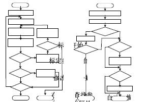
Figure 4 Calibration flow chart Figure 5 Monitoring flow chart
3 Design of the bottom software of the calibration system
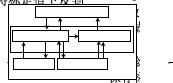
Figure 6 Low-level software design As shown in Figure 6, in order to increase the versatility of the low-level communication module, a modular design concept is adopted, the CAN Driver
Separated from CCP Driver. The Command processor is the main component of the CCP Driver; the DAQ processor is used to collect and periodically upload the current monitoring parameters of different DAQ tables as required. Two processors make up the CCP Driver of the controller,
It is the analysis and realization of the content of the calibration protocol. In order to ensure the reliability of CAN communication, CAN Driver uses a ring buffer mechanism and communicates interrupt subroutines and system tasks through operating system messages. By changing the CAN Driver, different ECU hardware platforms can be transplanted, and the new ECU can be calibrated, which increases the compatibility and versatility of the underlying communication module.
4 Conclusion The calibration diagnostic system designed in this paper integrates the functions of calibration, monitoring and diagnosis. On the basis of ensuring the flexibility of the system and the real-time communication, the use of software watchdog technology in the host computer realizes the rapid diagnosis and repair of the calibration system,
The automatic saving and loading of data can prevent the loss of calibration data, avoid repeated calibration work, and ensure the reliability of the entire calibration system. Experiments show that the system has high real-time performance, flexibility and reliability.
Usb Common Mode Choke,Magnetic Ring Inductor,Ferrite Core Inductor,Coilcraft Inductor
IHUA INDUSTRIES CO.,LTD. , https://www.ihua-coil.com