The development of the modern automobile industry has made a large number of in-vehicle electronic devices widely used in automobiles, such as car satellite navigation systems, car audio and video entertainment systems, body lighting systems, anti-theft systems, and automatic air conditioning systems. All kinds of in-vehicle electronic devices work stably and cooperate with each other, and a stable power supply system is required. Therefore, the high-performance vehicle power supply design is the guarantee for the reliable operation of the vehicle electronic equipment.
This article refers to the address: http://
The application environment of the ISO7637 standard vehicle power system is more complicated than the ordinary power system because the electromagnetic environment in the car is relatively bad. The electrical equipment of a car generates a large amount of electromagnetic interference during operation. These interferences have a wide frequency band and are transmitted to the power system through conduction, coupling or radiation, thereby affecting the normal operation of the electronic device. The worst cases are often caused by disturbances generated by the vehicle itself, such as the ignition pulse of the ignition system, generator and rectifier system. The international standard ISO7637 proposes an electrical transient conduction and test method along the power line for electrical interference caused by conduction and coupling in road vehicles and their trailers. It is suitable for 12V or 24V electrical system vehicles.
ISO7637 specifies five test pulses for the immunity requirements of automotive electronics on the power supply. Among them, pulse 1 is used to simulate transient interference generated by parallel inductive load during power failure, such as turning off the light or electric horn. The pulse 2a simulates the transient interference caused by the sudden disconnection of a parallel load during normal operation, and belongs to the positive pulse interference with faster speed and less energy. Pulse 2b simulates the moment when the ignition is cut off, the DC motor becomes a generator, and the resulting transient phenomenon belongs to low-speed and high-energy pulse interference. Pulse 3a/3b simulates the interference generated during the closing and opening of various switches and is a series of high-speed, low-energy small bursts. Pulse 4 simulates the voltage drop caused by the start of a large current load on the vehicle. Pulse 5 simulates large energy pulse interference caused by load dumping.
The specific design of the power supply circuit must be targeted to the power supply system for the whole system. In addition to the elimination of interference sources, the most important thing is to improve the anti-interference ability of the power system. Commonly used methods for improving the anti-interference ability of the power supply system include: filtering by the absorption method to eliminate positive pulse interference, the device used may be a thermistor, a TVS tube, etc.; for a negative pulse, an increased capacitance capacity may be used. Use energy storage to resist interference. For power supply drop interference, the filter capacitor of the power supply can be increased. When the cost and performance specifications are met, the power chip with wide input range is selected as much as possible.
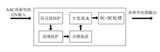
Figure 1 power system block diagram
Aiming at the immunity requirements of ISO7637 for automotive electronic equipment on the power supply, a reasonable 12V power supply system scheme is given here. The system block diagram is shown in Figure 1.
The power system includes anti-reverse protection, surge protection, common mode turbulence, π-type filtering and DC/DC processing. The working principle of each part is as follows: Anti-reverse protection can be realized by using a common diode. Surge protection includes a PPTC and TVS tube that effectively suppresses interference similar to Pulse 5. The PPTC is a thermistor and the resistance increases with increasing temperature. TVS is a transient voltage suppression diode, and its specific selection principle will be described in detail later. When a pulse 5 interferes into the power line, the TVS will act to shunt the instantaneous current flowing to the back-end circuit, while the protected back-end voltage is limited to the clamp voltage across the TVS. The operating speed of the PPTC is slower than that of the TVS. Under the action of a large current, the PPTC is high-resistance, and the circuit of the latter stage is disconnected, which can reduce the TVS effusion time and protect the TVS. The common mode turbulence part is a common mode choke coil, which can effectively suppress high frequency common mode noise, improve the anti-electromagnetic interference of the power supply circuit, and suppress the external emission interference of the circuit itself. The π-type filter circuit further filters out noise and purifies the power entering the back-end circuit. DC/DC processing completes various types of power conversion according to actual applications, such as 5V, 3.3V, 1.8V, and the like. This power system uses the vehicle-grade DC/DC chip A8498. It has a wide voltage input range of 8 to 50V. The output is adjustable from 0.8 to 24V. The output drive capability is 3A, which can meet the needs of various back-end loads. There are two large and one small capacitors on the input pin side. In addition to filtering noise, it also has the function of energy storage. The high polarity capacitor C5 uses high quality tantalum capacitor. Because the minimum operating voltage of the A8498 is 8V, the voltage drop will reach 6V when the pulse 4 is encountered. To ensure that the A8498 can still provide normal output in the short moment of the drop, the capacitance of the large capacitor should be large enough at the input voltage. Provides sufficient energy storage when dropped. The actual test results of the scheme indicate that the value of the capacitor C5 is at least 220 μF.
The detailed circuit design of the power system is shown in Figure 2.
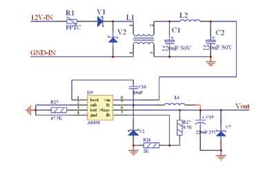
Figure 2 power system circuit diagram
Surge pulse similar to pulse 5 has the characteristics of large energy and short action time, which will cause irreparable damage to the system circuit. Therefore, the suppression of pulse 5 is the focus of the entire front-end protection circuit design. First of all, to determine the maximum input voltage of the entire protected system, the maximum withstand voltage of the A8498 is 50V, so in the event of a surge of pulse 5, the TVS tube must be able to clamp the voltage below 50V. The TVS tube selection has several important parameters: the withstand reverse voltage Vrwm, the reverse breakdown voltage Vbr, and the suppression voltage Vc. Vrwm must be greater than the normal input operating voltage of the system to prevent the TVS tube from operating on the normal input voltage. Vbr and Vc are smaller than the maximum withstand voltage of the protected circuit and as close as possible to this value. The rated maximum power of the TVS tube must be greater than the maximum power similar to pulse 5 interference to prevent damage. In this design, the TVS tube of model 5KP30A is selected. The Vrwm value of the tube is 30V, the Vbr is between 33.3 and 38.3V, and the Vc is 48.4V. On the related in-vehicle electronic equipment, some auto manufacturers will also require the equipment to have a certain overvoltage working time. This maximum overvoltage value is also a parameter of TVS selection, and Vbr is preferably slightly larger than the maximum overvoltage value. In short, when selecting a TVS tube, it is necessary to combine the electrical parameters and cost of the entire circuit.
Program test
The second part of ISO 7637 gives specific test methods for electrical interference caused by conduction and coupling along the power line. For test results, the following standard terminology is used to describe the immunity capability of the device. Class A: The device under test can perform all of its pre-designed functions during the process of applying interference and after the interference is removed. Class B: The device under test or system can perform all of its pre-designed functions during the process of applying interference. However, there may be one or more indicators that exceed the specified deviation. After the interference is removed, all functions are automatically restored to normal operation. Class C: The device under test or system does not perform one or more of its pre-designed functions during the application of interference, but automatically returns to normal operation after the disturbance is stopped. Class D: During the process of applying interference, the device or system under test does not perform one or more functions pre-designed. After the interference is removed, the external reset action can be used to restore the normal operation state. Class E: The device or system under test cannot perform one or more of its pre-designed functions during the process of interference and interference cancellation, and the reset does not restore the device or system to normal operation. Maintenance must be performed (ie Hardware damage occurred).
For different in-vehicle electronic devices, each car manufacturer has different requirements for the immunity level of the test equipment. For car DVD, the radio system requires at least Class C, and the body control and alarm equipment are Class A. In general, at least C or above. This program is applied to our self-designed car DVD audio and video system, and has carried out ISO7637 Class 5 pulse test at Shanghai Metrology Institute. The test results show that the scheme is reliable and the audio-visual system has an anti-interference ability of at least class B.
Conclusion The improvement of the anti-interference ability of the vehicle power supply is essential for the stable operation of the entire vehicle electronic device. The hardware design must comprehensively consider the various interferences simulated by ISO7637. The software design must have the ability to eliminate memory loss caused by interference in the whole system. A good combination of hardware design and software design can better improve the anti-interference ability of the entire system. The ISO7637 power supply design scheme given in this paper has high performance and low cost, which can meet the application requirements of various 12V automotive electronic devices. The program is currently used in our automotive products.
The biggest feature of the temperature regulating valve is that it only needs an ordinary 220V power supply and uses the energy of the regulated medium to directly automatically regulate and control the temperature of steam, hot water, hot oil and gas. It can also be used to prevent overheating or heat exchange. The valve has the advantages of simple structure, convenient operation, wide temperature regulation range, fast response time and reliable sealing performance, It can be adjusted at will during operation, so it is widely used in hot water supply in chemical industry, petroleum, food, light textile, hotels and restaurants.
Temperature Regulating Valve,New Needle Valve,Marine Butterfly Valve,Valve Pressure Gauge
Taizhou Jiabo Instrument Technology Co., Ltd. , https://www.taizhoujiabo.com