In DDR PCB design, it is generally necessary to consider equal length and topology. Equal lengths are better handled, and giving a certain isometric accuracy is usually what the PCB designer can do. However, for different rates of DDR, it is critical to choose the right topology. The T-type topology and the daisy-chain topology that are often used in DDR cabling are described below. The differences between these two types of topology and the points to note are mainly described below.
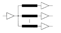
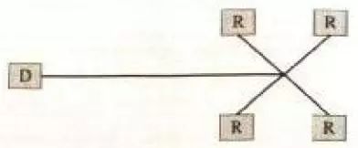
T-type topology, also known as star topology, where the receiving end load and trace length of each branch of the star topology are consistent as much as possible, which ensures that each branch receiving end receives signals simultaneously, each branch Termination resistors are generally required. The resistance of the termination resistor should match the characteristic impedance of the connection. The star topology can effectively avoid clock, address and control signal out of sync problems.
The daisy-chain topology is different from that of the star topology. The daisy-chain topology does not keep the length of the driving end to each load as consistent as possible, but ensures that the length of each driver-to-signal trunk is as short as possible. The characteristics of the daisy-chain topological structure, at the expense of the clock, address and control signal synchronization, but the biggest feature is to reduce the length of each load branch route as much as possible to avoid the reflection of the branch signal on the main signal interference.
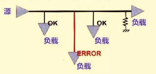
In the case where the signal frequency is lower than 800 MHz, the above two topologies can meet the system performance requirements. However, when the signal rate reaches 1000MHz or even higher, the T-type topology cannot meet the performance requirements. The reason is that the T-type topology is too long for the length of the tributary line. It is difficult to achieve impedance matching with the main channel without adding a termination resistor. In order to achieve impedance matching for each triode, the termination resistance is increased. The amount of work and cost in circuit design is something we do not want to see. Therefore, when the high-speed signal uses the T-type topology, especially when Stub>4, the interference of the branch signal on the trunk signal is very serious. DDR2 uses DDR2 topology and DDR3 with low speed requirements.
The daisy chain topology is mainly used in DDR3. The main advantage of daisy chain topology is that the branch routing is short. It is generally considered that the daisy chain branch length is less than 1/10 of the signal's rising edge propagation length, which can effectively weaken the branch signal. The interference of the reflection to the trunk signal is not the same in different books. In principle, the length of the trace is less than 1/6-1/10 of the propagation length of the rising edge. In the actual design, we certainly hope that the shorter the length, the more it is good. The daisy-chain topology can effectively suppress the reflected signals of the tributary, but compared with the T-type topology, the clock, address, and control signals of the daisy-chain topology cannot reach different DDR chips at the same time.
In order to solve the problem of asynchronous synchronization of signals in the daisy-chain topology, the new standard of DDR3 incorporates time compensation technology to achieve signal synchronization through DDR3 internal adjustment. When the signal frequency is as high as 1600MHz, the T-type topology has been powerless, and only the daisy-chain or its derived topology can meet such performance requirements. The general DDR3 will propose an improved topology with a daisy-chain topology. The Fly-by topology requires a stub length of Stub = 0, and Fly-by has better signal integrity.
In the practical application of the daisy-chain topology, in order to suppress the Stub from being too long and the branches are too many to interfere with the reflection of the trunk signal, and to strengthen the driving ability of the trunk signal, the resistance circuit is generally set aside at the end. The pull-down resistor at the end increases the power consumption of the IO port. Therefore, the pull-up resistor is used for termination. The Thevenin equivalent voltage of the signal driving part is calculated as the pull-up voltage Vtt, and Rt is the equivalent resistance of the driving part. Generally, the pull-up voltage is taken as the general value of the IO driving voltage, that is, Vtt=Vddr/2.
Connecting Terminals,Micro Connecting Terminal,Aluminum Connecting Terminals,Connecting Copper Terminal
Taixing Longyi Terminals Co.,Ltd. , https://www.longyicopperlugs.com