The mixed-signal processing module is a SIP chip introduced by Orbit, which uses a three-dimensional packaging technology for a specific (customizable) mixed-signal module. This article describes the configuration and application of mixed-signal modules.
1 chip introductionThe three-dimensional packaging technology used in the mixed signal module encapsulates a specific circuit into a chip. The chip described in this paper includes address switch decoding, analog signal input, and analog signal adjustment output. The analog signal is input to the analog switch, and the address information selects two channels to input the analog signal to the differential op amp for amplification output. The internal decoding delay and sampling circuit can sample the system error. After the sampling is completed, the sampling circuit works in the hold state. The system error output is connected to the op amp reference terminal through the internal switch for output compensation, so that when the subsequent system works, The output of each op amp is the output after system error correction to ensure the stability and consistency of the output.
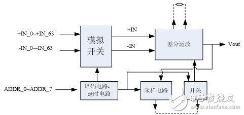
Figure 1: Functional Block Diagram of the Mixed Signal Module
The module chip adopts QFPG220 PIN package form, each sub-function module is connected in the substrate, and the analog signal input, decoding address, op amp setting end, sampling output, switch input and analog output end are used as pin signals.
2 chip function applicationAs mentioned above, the module chip is a complete electronic system, which can be applied to signal adjustment (system error sampling correction, analog signal amplification output) of multiple analog signal inputs (differentiable signals). The following describes the module chips separately.
2.1 analog switch section
The mixed signal module includes 64 analog positive inputs and 64 analog negative inputs. Internally, 8 sets of high-speed analog switches are connected to the input terminals. Internal Decode generates a chip select and address signal to determine the strobe's two channels to input the signal to the differential op amp. The input signal amplitude is -10V~14V, and the op amp gain is set to 100 times inside the module. It is recommended that the difference between the two input terminals of the differential op amp does not exceed ±100mV.
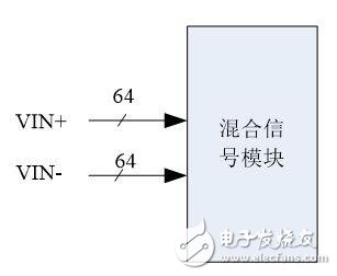
Figure 2: Mixed Signal Module Analog Input
2.2 decoding address part
The address signal of this module is 8 channels, of which the upper 4 bits are used for analog switch chip select output, and the lower bit is used for analog switch address output. The address truth table is shown in the following table:
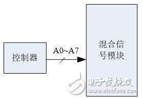
Figure 3: Mixed Signal Module Address Signal Input
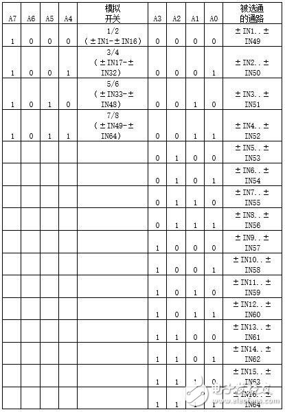
Table 1: Analog Channel Decoding Truth Table
2.3 op amp gain adjustment terminal
The signal processing module differential op amp has two gain adjustment terminals for pin output. The op amp has been internally amplified by 100 times in the module. If necessary, the gain can be adjusted by connecting resistors at both ends.
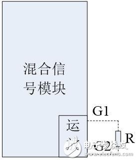
Figure 5: Mixed signal module sample-and-hold circuit external terminal
Since AC power cord is output of high voltage electric power, there is a risk of electric shock injury, therefore, All the AC power cord must comply with safety standard to produce. AC (Alternating Current) Power cord is to transmit high voltage. It is used to drive machinery or home appliances.
AC Power cord,power cable, batter cable, power cord
ETOP WIREHARNESS LIMITED , https://www.wireharness-assembling.com