The application of robots is becoming more and more extensive, which plays an important role in industrial production and efficiency. Industrial robots mainly use servo motors for motion control to implement moving and grabbing tools. This article will discuss in detail the characteristics of servo motors and the corresponding control principles of different types of servo motors.
Principle of motion control
Motion control is closely related to robots. Robots in industrial applications must move themselves through actuators made up of multiple motors to perform tasks or grab tools through the robot arm.
The motion control system of a robot usually consists of a motor controller, a motor drive, and a motor body (mostly a servo motor). The motor controller has intelligent calculation functions and can transmit commands to drive the motor. The drive provides boost current and drives the motor according to controller commands. The motor can move the robot directly, or it can be moved by a drive train or chain system.
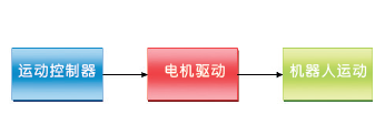
Figure 1: The motion control system of the robot.
Output type
Mobile robots are often used to explore a wide area of ​​land and can be moved using a variety of propellers, machine feet, wheels, tracks or robotic arms. For example, various NI display platforms, including VINI, VolksBot and Isadora. These robots use the Mecanum wheel, the general wheel, and the robot arm. For embedded control, it can be integrated with real-time controllers and FPGAs through embedded platforms such as NI CompactRIO. CompactRIO also includes a reconfigurable chassis that can accommodate a wide variety of I/O configurations, including sensor inputs and motor control.
The VINI is a robotic platform that uses omnidirectional wheels and can travel in multiple directions. In addition to advancing and retreating like a conventional wheel, the omnidirectional wheel can also rotate the axle in the opposite direction, traveling in any direction. This wheel is commonly used in applications such as automatic stackers that must be able to move in tight spaces.
VINI is also a map depicting robot that performs path planning and data processing operations with NI industrial-grade controllers and CompactRIO. Embedded industrial-grade controllers provide laser-scanned maps and perform machine vision processing, allowing CompactRIO to receive sensor data and control servo motors on the camera system.

Figure 2: VINI robot.
The wheels on the VolksBot were developed by the Fraunhofer Institute in Germany.
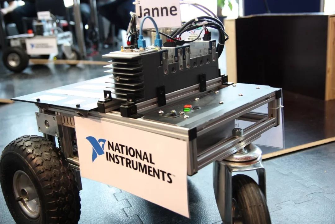
Figure 3: RT3 VolksBot developed by the research institute of the Fraunhofer Institute in Germany.
Isadora is a humanoid robot that can dance and manipulate the reduced version of the robot to obtain input data. Then start moving your robot arm and torso to mimic the movement of the reduced version of the robot. Isadora uses two sets of CompactRIOs, one for simulating recorded motion and the other for robots to reproduce motion trajectories.
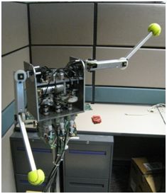
Figure 4: Isadora dancing robot.
Servo motor control principle and its type
Servo motors are a common type of motor in robotic applications. The basic control principle is to use the control loop and combine the necessary motor feedback to assist the motor to enter the desired state, such as position and speed. Since the servo motor must know the current state through the control loop, its stability is higher than that of the stepper motor.
There are different types of servo motors - brush and brushless. The difference between a brushed servo motor and a brushless servo motor lies in its communication mechanism. The working principle of the servo motor is based on the reverse magnetic force, which in turn moves or establishes the torque. The simplest examples are fixed magnetic fields and rotating magnetic fields. By changing the direction of the current flowing through the magnetic field, the magnetic pole can be changed and the magnetic pole (rotor) can be rotated. Change the direction of the current of the coil, the so-called "commutation".
Brushed servo motor
The control principle of a brushed motor is to change the current in the motor coil by a mechanical brush. Since the brush motor can change the direction of the incoming current, it can be powered by a DC power source (DC). Brushed servo motors can be divided into 2 groups of parts:
The motor casing has a field magnet, that is, a stator.
The rotor (Rotor) is composed of a coil with an iron core in the middle and connected to the current transformer.
The brush contacts the current transformer and directs current into the coil. After a period of use, the brush can wear and generate friction to the system; however, this does not happen in brushless servo motors.
Brushless servo motor
Most brushless servo motors use AC power (AC). The control principle of the brushless servo motor is to place the iron core on the outside. When the rotor becomes a temporary magnet, the stator becomes a wound iron coil. The current of the external circuit will be reversed at the given rotor position. Therefore, this servo motor is driven by alternating current. Of course, there are also brushless DC servo motors. These motors typically have some electronic switching circuitry that can be converted for incoming DCs. Brushless servo motors are more expensive, but have no wear problems.
Stepper motor
In robotic motion applications, stepper motors are not as popular as servo motors, but they are still important examples of motors and are easier to use. Stepper motors are slower and more accurate than servo motors. The stepper motor has a series of built-in Brushless teeth, which can pull the rotor by the next set of brush teeth after the current passes to change the electromagnetic charge. The former set of brush teeth pushes the rotor, thus the stepper motor. power ups.
Compared to the servo motor, since the stepper motor can be accurately controlled by the number of brush teeth (that is, equal to the distance moved), feedback is generally not required. However, the brush may be missing due to obstacles, so the encoder can be used as feedback.
Motion controller and software architecture
Many manufacturers have built their own drive systems to control robots. When considering the motion control system in a robot application, you can first understand the initial mesh loop, as shown in the following figure.
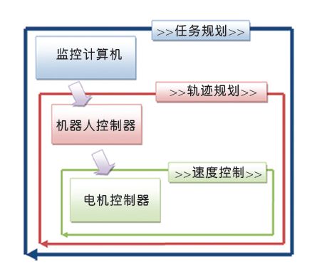
Figure 5: Motion Control Software Architecture.
As for the higher-order functions of robot mission planning, it is to let the robot's actions reach the ultimate goal. It may encompass multiple sets of targets in a single instruction or allow the robot to enter a specific location. If the robot is in a Tele-operated architecture, these instructions are most likely to be transmitted via an off-board computer, and the subsequent actions or actions of the robot can be selected for this human operation. In fully automated robots, task planning may also be performed directly on the board, depending on the algorithm used for decision making.
When planning a path, there are often questions such as "How should I get to the destination to complete this task?" or "How should I move the robot arm to that position?" This problem can be solved by the robot motion controller.
Once the destination and travel speed are clear, the servo motor controller will issue a control signal (PWM or current, etc.) to the actual motor drive to get it to its destination. The control functions are generally constructed by PID. Please also note that security features should also be implemented at this time. For example, if a robot traveling at high speed detects a human on the current path, an emergency signal should be issued to stop the motor or immediately brake.
Pc Speaker,Gaming Pc Speakers,Pc Speaker Rgb,Pc Speaker Usb Powered
Comcn Electronics Limited , https://www.comencnspeaker.com