1 Composition and working principle of constant current source The constant current source circuit is shown in Figure 1. In the figure, A is a high-precision op amp, Q1 and Q2 are power MOSFETs, and the load is inductive. The NE555P constitutes a pulse-position modulator that operates in an unsteady mode, and its oscillation frequency is modulated by a signal input from the 5-pin. The control terminal 5 adds the modulation signal VΩ (this terminal allows the voltage of 0~EC to be applied), so that the threshold level Vth1 and the trigger level Vth2 of the timer are changed with VΩ, namely: 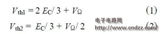
Therefore, the charging time and discharge time of the timer capacitor C2 are controlled by the modulation signal VΩ; the position and pulse width of the positive pulse of the 3-pin output will change with the change of the modulation signal VΩ, and the double modulation of the position and width of the pulse is realized.

Figure 1 Constant current source circuit
The control voltage Vi is divided by R1 and R2 and applied to the input terminal of the operational amplifier A. The output signal of the operational amplifier is used as the modulation signal of the NE555P.
The PWM signal of the NE555P 3-pin output controls Q1, and drives Q1 and Q2 to operate alternately in the switch state; the operating frequency and duty cycle of Q1 are equal to the frequency and duty cycle of the NE555P 3-pin output voltage signal. When Q2 is turned on, D is in the off state, DC voltage EC is added to both ends of D, and LC is filtered to supply power to the load; when Q2 is off, the input voltage is 0, D is turned on under the action of loop inductance, which constitutes freewheeling. In the loop, D can also weaken the back EMF generated across the inductive load when the output signal voltage transitions from a high level to a low level. RS is the sampling resistor. Therefore, after the control voltage is operated by the op amp, the duty cycle of the pulse modulator output pulse signal is controlled, and the switching time of Q1 and Q2 is changed, thereby controlling the magnitude of the output current.
From Figure 1, according to the characteristics of the op amp: 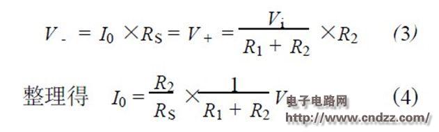
When RS = 1Ω, R1 = 24k, and R2 = 16k, I0 = 0.4Vi. When the input voltage Vi changes from 0 to 5V, the output current I0 will change from 0 to 2A. It can be seen that the output current is mainly determined by R1, R2 and RS, regardless of the load size.
2 Test results In order to test the performance of the constant current source, the author conducted an experimental study. The power supply adopts DC 12V 2A high-precision regulated power supply. In component selection, A selects high-precision op amp, the resistor uses one-thousand-thin precision precision resistor, and the sampling resistor selects non-inductive wirewound resistor with good temperature stability. The load used in the experiment is inductive, the inductance is 180mH, the static resistance is 4Ω, and the parameters of the MOSFET are shown in Table 1.
Table 1 MOSFET parameters
2. 1 relationship between output current and input voltage When RS = 1Ω, R1 = 24k, R2 = 16k, when the input voltage Vi changes from 0~5V, the theoretical calculation and the actual measured output current I0 vary with the input voltage Vi. Figure 2 (match), the output current is linear with the input voltage.
Figure 2 Relationship between output current and input voltage
2. 2 relationship between sampling resistance and output current When R1 = 24k, R2 = 16k, input voltage Vi is 5V, the relationship between the measured resistance and output current is shown in Figure 3. The smaller the sampling resistance, the larger the output current, the resistance The power consumption also increases accordingly; vice versa. It is basically consistent with theoretical calculations.
Figure 3 Relationship between sampling resistance and output current
2. 3 Other performance measurements The constant current source output current is linear with the duty cycle of the PWM signal. The larger the duty cycle, the larger the output current (see Figure 4); the ripple current < 3mA; the load regulation rate < 1 %.
Figure 4 Relationship between duty cycle and output current
3 Conclusion Select the appropriate component parameters, when the control voltage changes from 0~5V, the output current I0 of the constant current source circuit will continuously change in the range of 0~ + 2A; the power supply has high efficiency, good linearity and simple structure. Safety (output voltage < 12V), stable advantages. This constant current source can be used as a driving power source for a magnetorheological damper, and can also be applied to other fields.
More about NE555P data: IC query network http://
China Switch Cabinet,Battery Charging Cabinet manufacturer, choose the high quality Solar Battery Storage Box,Solar Battery Cabinet, etc.
Switch Cabinet,Battery Charging Cabinet,Solar Battery Storage Box,Solar Battery Cabinet
Shenzhen Hongjiali New Energy Co., Ltd. , https://www.hjlcharger.com