After completing the last obstacle avoidance robot project based on simple electrical circuits, we will be making a third PVC robot project. This is a special robot. First of all, its control circuit is a little more complicated than the previous one. It is made up of electronic components. Secondly, this robot no longer uses traditional batteries as the power source, but uses green solar energy as the energy source. In addition, the power-driven mode of this project is quite special - moving in a vibrating manner.
This article refers to the address: http://
This project is mainly for beginners who are somewhat unfamiliar with electronic circuits. It enables everyone to master electronic production based on electronic components, understand basic electronic knowledge, understand simple circuit principles, and master basic circuit soldering techniques. If you are already familiar with this, you can skip this section.
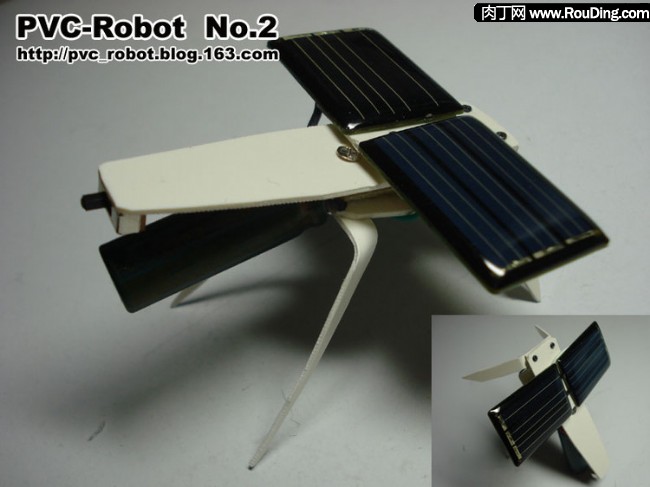
This is a special mobile robot with solar energy as its power source, that is, using solar cells as the power source, and the vibration effect of the eccentric pendulum motor as the driving force.
The following is the effect video, the previous paragraph is the effect of testing under the light (incandescent), the latter section is the effect in the sun.
Because of the similar appearance and the buzzing sound during the vibration, I gave the solar powered robot of this project another nickname - the sun-bathing mosquito, hehe.
The Taobao address of this project kit: http://item.taobao.com/item.htm?id=9284864243
First, the basic principle
1.1, the driving principle
1.2, mechanical structure
1.3, circuit principle
1.3.1, circuit symbol
1.3.2, electronic components (resistors, capacitors, diodes, three-stage tubes, vibration motors, solar cells)
1.3.3, principle analysis (conventional analysis, analogy analysis)
Second, preparation work
Third, the production process
3.1, circuit welding
3.2, circuit test
3.3, structure production
3.4, install the circuit board
3.5, vibration motor
3.6, solar cells
3.7, power switch
3.8, the whole machine assembly
3.9, the whole machine effect
3.10, perfect structure
Fourth, the effect of the show
Five, frequently asked questions
Project summary
First, the basic principle The solar robot of this project uses solar cells as the power source, and relies on the vibration waves from the vibration motor with eccentric pendulum to move. 1. Drive principle The power of the robot of this project comes from the vibration motor, which is the same as the drive principle of our No. 0 robot. For details, please refer to here: PVCRobot No. 0 robot drive principle The so-called vibration motor here is actually realized in our mobile phone. The vibrator of the vibrator is driven by a rotating motor to drive a pendulum on the eccentric. Since the center of gravity of the pendulum is on one side of the rotating shaft, during the rotation of the motor, it will be due to the pendulum The weight continuously circulates around the shaft to generate a centrifugal external force (ie, alternating up and down, left and right swings), causing vibration of the motor.
![[Project] 5.2, PVCRobot [No. 2] mosquitoes in the sun, solar powered robots PVCRobot PVCRobot](http://i.bosscdn.com/blog/ac/57/87/3da636f2c474325ae3e5394e47.jpg)
In the figure below, the two vibration motors on the left are connected to the eccentric pendulum on the ordinary motor, while the flat on the right actually fuses the motor and the pendulum. The effect is equivalent to the left motor being placed vertically, but the structure is more Compact.
![[Project] 5.2, PVCRobot [No. 2] mosquitoes in the sun, solar powered robots PVCRobot PVCRobot](http://i.bosscdn.com/blog/65/33/53/896e2a6a387e228e4d6738e1b3.jpg)
2. Mechanical structure The structure of the robot of this project was originally designed by adopting the "three-point support" method, that is, a pair of front feet, and then the tail (electronic components: electrolytic capacitors) landed.
![[Project] 5.2, PVCRobot [No. 2] mosquitoes in the sun, solar powered robots PVCRobot PVCRobot](http://i.bosscdn.com/blog/04/b1/76/44275068496b56079915896bf4.jpg)
Later, during the actual test, it was found that the center of gravity was relatively centered due to the far location of the tail, so that the overall balance was relatively stable, and the amplitude of the movement was insufficient during the vibration. Later design changed to add two more hind legs, which can be used in three ways:
1) "four-point support": four-legged squat, relatively stable, with a small movement;
2) "Three-point support": the hind legs stand, which is relatively stable and has a large movement range;
3) "One point support": The tail is independent of the ground, very unstable, and the maximum movement.
These three different scenarios are also demonstrated in the video above.
That is to say, adding two hind legs, it looks like a mosquito, and the nickname of the robot "mosquito" is also named.
![[Project] 5.2, PVCRobot [No. 2] mosquitoes in the sun, solar powered robots PVCRobot PVCRobot](http://i.bosscdn.com/blog/b5/22/47/ceac515ac22a760def5dc8a7aa.jpg)
In the case of a certain weight, the more unstable the structure, the greater the amplitude of the movement under the influence of vibration. However, since the device used for vibration is a motor with a pendulum, there is a tendency to rotate during the vibration. If an unstable support structure is used, it is easy to rotate in place.
To change this situation, you can: adjust the mounting position of the vibration motor
If the vibration motor is installed from the direction of the now parallel body (one-line type) to the vertical body (cross type), the tendency of the rotation will become the power of forward or backward, and the robot will be caused by the vibration. "Turn" changes to "forward" or "backward" movement.
If you want to change the forward or backward, just change the positive and negative poles of the motor, that is, change whether the motor rotates clockwise or counterclockwise; if the pendulum position of the vibration motor is not exactly at the center axis of the robot body, there will be a slight The rotation, but the effect of this move is better, with a little turning.
![[Project] 5.2, PVCRobot [No. 2] mosquitoes in the sun, solar powered robots PVCRobot PVCRobot](http://i.bosscdn.com/blog/4f/e7/0c/6324df99d5a9587dc81b1584d7.jpg)
In addition, it is mentioned here that if a flat vibrator is used, it is inevitable that the above-mentioned rotation condition will occur, because the flat vibrator is actually equivalent to the vertical movement of the above-mentioned vibration motor with the rotating shaft perpendicular to the ground. However, the flat vibrator cannot adjust the mounting orientation (only the flat horizontal surface is attached to the surface of the object) due to the shape limitation, that is, the orientation cannot be resolved by changing the orientation as described above. Of course, if you specifically pursue the effect of rotation, it is another way of thinking.
3. Circuit principle The circuit of this project is more complicated than the simple electrical circuit of the previous project. In addition to special solar cells and vibration motors, there are several resistors, capacitors, diodes, and three-stage transistors. Electronic components inside.
![[Project] 5.2, PVCRobot [No. 2] mosquitoes in the sun, solar powered robots PVCRobot PVCRobot](http://i.bosscdn.com/blog/ec/99/ad/41fc0e8c963d0e4eef8bf8afd5.jpg)
For those who are familiar with electronic circuits, it must be very simple to read this circuit diagram. If you haven't touched the electronic circuit, it doesn't matter. I will explain it carefully. Interested friends can listen to me slowly. If you are already a friend, please skip the following paragraph. Of course, there may be some friends who say, "I don't go into the circuit principle. Anyway, I will assemble according to the circuit diagram." This is of course possible (I used to be ^_^ when I first learned the radio). Below I will explain it with a simple and common metaphor. Some metaphors may not be very appropriate, but they help to understand some abstract and raw content.
1) Circuit Symbols We must first look at the circuit diagram. The following figure shows the electronic components corresponding to each symbol.
![[Project] 5.2, PVCRobot [No. 2] mosquitoes in the sun, solar powered robots PVCRobot PVCRobot](http://i.bosscdn.com/blog/bc/db/f0/344874f98c6549250131d0658d.gif)
In addition, in addition to understanding what electronic components each symbol represents, we also need to understand the basic circuit connection expression. Especially for the way the cross line is represented:
a) A set of intersecting lines on the left side of the figure below, with a dot in the middle, indicating that the horizontal and vertical lines are connected to each other;
b) The two sets of cross lines on the right side of the figure below, one set has no dots in the middle, and the other set has an arc (which seems to be like the past). Both groups represent the same meaning—the horizontal and vertical lines They are not connected to each other.
![[Project] 5.2, PVCRobot [No. 2] mosquitoes in the sun, solar powered robots PVCRobot PVCRobot](http://i.bosscdn.com/blog/7d/3d/4c/6d42a2e83f7599538e90010a03.jpg)
2) Electronic components
Let us look at the several electronic components involved in the circuit of this project.
(1) Resistance
The role of the resistor can be understood as reducing the current.
The two symbols in the figure below are the electronic symbols of the resistor.
If the current is compared to a water flow, the resistance can be seen as a device that transfers the flow of a large water pipe to a small water pipe (water flow reducer). A relatively large water flow passes through the device and becomes a relatively small water flow. .
![[Project] 5.2, PVCRobot [No. 2] mosquitoes in the sun, solar powered robots PVCRobot PVCRobot](http://i.bosscdn.com/blog/b1/19/79/e8ba06a5740428a848e0747716.jpg)
Note: In fact, it is not possible to simply reduce the flow of water by means of a large water pipe to connect a small water pipe. This will only make the water flow more urgent and faster. The above metaphor only hopes to simplify the expression by ignoring other factors.
The basic parameter of the resistance is called the "resistance value", which can be understood as the degree to which the large water flow can be turned into a fine water flow, that is, the larger the resistance value, the finer the water flow that can be converted.
The value unit of the resistance "resistance":
a) The basic unit is: ohm (symbol: Ω);
b) The unit of the larger point is: kilo ohm (symbol: KΩ, abbreviated as K);
c) The larger unit is: mega ohms (symbol: MΩ, M for short).
The conversion relationship is: 1MΩ=1,000KΩ=1,000,000Ω
The resistance of the resistor used in this project is 2.2K.
(2) Capacitance
The role of a capacitor can be understood as the storage current (actually a charge).
Capacitors have two pins, generally divided into two types, one is a common capacitor without polarity; the other is an electrolytic capacitor (abbreviated as electrolysis) whose two pins distinguish positive and negative polarity, and its positive electrode The pin of the sex must be connected to the positive pole of the power supply, and the pin of the negative polarity must be connected to the negative pole of the power supply. In the following electronic symbols, the one on the left is an ordinary capacitor, and the two on the right are electrolytic capacitors (two different representations, with a plus or a hollow side being the positive).
![[Project] 5.2, PVCRobot [No. 2] mosquitoes in the sun, solar powered robots PVCRobot PVCRobot](http://i.bosscdn.com/blog/16/12/10/e3858370b0a66727e939b8cde7.gif)
If the current is compared to the current, the capacitor can be seen as a “water storage deviceâ€, while the electrolytic capacitor is a “reservoir that defines the direction of the water flowâ€. There is a special inverted trapezoidal container in the reservoir. Water is injected into the pool. When the water reaches a certain level, due to the problem of gravity balance, the inverted trapezoidal container will pour out all the water at one time, and the water will overflow from the other outlet.
![[Project] 5.2, PVCRobot [No. 2] mosquitoes in the sun, solar powered robots PVCRobot PVCRobot](http://i.bosscdn.com/blog/12/74/4b/6b1fefb1decf2063f402e2a3b5.jpg)
The basic parameter of the capacitor is called “capacity value†and can be understood as how much water can be stored. That is, the larger the volume, the more water can be stored (or the more water needs to be injected to fill the water, the water can be Export outflow).
The numerical unit of the capacitance "capacity value":
a) The basic unit is: Farah (symbol: F, less used);
b) The smaller unit is: milli-method (symbol: mF, less used);
c) The smaller unit is: micro-method (symbol: μF, commonly used);
d) The smaller unit is: leather method (symbol: pF, commonly used);
e) The smallest unit is: nano method (symbol: nF, less used).
The conversion relationship is:
1F=1,000mF=1,000,000μF=1,000,000,000pF=1,000,000,000,000nF
1μF=1,000pF
The capacitance of the electrolytic capacitor used in this project is: 4700μF.
(3) Diode
A diode has two pins (hence the name), and the basic function can be understood as allowing only one polarity of current to pass. The LED light-emitting diodes used in this project can emit light in addition to this function.
The two pins of the diode are positive and negative. Only the positive current can pass unidirectionally from the positive terminal of the diode, or only the negative current can pass through the negative terminal of the diode.
The electronic symbol of the diode, one end of the bell is positive. In the figure below, the one on the left is a normal diode, and the two on the right are LEDs (two different representations, with arrows indicating the illuminating effect).
![[Project] 5.2, PVCRobot [No. 2] mosquitoes in the sun, solar powered robots PVCRobot PVCRobot](http://i.bosscdn.com/blog/54/06/4c/899f5d8a85b8e74154a59dbf6c.jpg)
If the current is compared to a water flow, the diode can be regarded as a valve that "automatically controls the water flow direction according to the water pressure." When the pressure of the water flow reaches a certain level, the water flow will open the valve to allow the water to flow through, but at the same time, the water flow It will not be poured into the water inlet (the water inlet is higher than the water outlet to achieve one-way flow; a professional analogy is a valve called “check valve†that can control the water to not flow back).
![[Project] 5.2, PVCRobot [No. 2] mosquitoes in the sun, solar powered robots PVCRobot PVCRobot](http://i.bosscdn.com/blog/e5/d1/87/a3f9363b36afe30baae057c895.jpg)
The function of the diode in this project is the function of a valve. It is necessary to set certain conditions for the valve to open. This can be understood as the water volume is sufficient to reach a certain water pressure, and the valve is opened to allow the water to flow.
The diode "opens the valve" is actually called "on", that is, when the voltage across the diode reaches a lower limit, the diode is turned on to allow current to pass. Generally, the on-voltage of a diode of a common silicon material is 0.7V (volts), and the on-voltage of the LED light-emitting diode used in this project is about 2V (volts), that is, when the LED is about 2V (volts). The LED is turned on and emits light at the same time.
The reason why LED light-emitting diodes are used in this project is because we want to set a valve with a conduction condition of about 2V. If a non-light-emitting diode of a general silicon material is to be used, since the on-voltage condition is relatively low, and the overall on-state condition is 2V, we need to connect three common diodes in series (each turn-on voltage is 0.7, The three are 2.1V). That is to say, three common silicon diodes can be used in place of one LED light-emitting diode. Of course, in order to simplify and reduce the number of components, we recommend using LED light-emitting diodes.
It should be reminded here that this project proposes to use red-emitting red LEDs. This diode has relatively low on-voltage, while other colors have higher on-voltage (close to or even 3V, green and green, The yellow yellowish light is relatively high, while the white light has the highest color of other colors. Otherwise, it may affect the effect - that is, affecting the sensitivity of the valve, which may make the valve difficult to open.
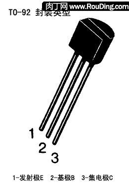
(4) Transistor
The triode has three pins (hence the name), and the basic role in this project is to understand that when the voltage of the "control pin" reaches a certain level, the other two pins are connected to allow current to pass.
The two pins of the triode are different. The "control pin" is called the "base" and is represented by the letter "B". In addition, the pin that is often connected to the power supply is equivalent to the current that is introduced. "Pole", denoted by the letter "E"; there is also a pin that is the output current to the target, called the "collector", which is indicated by the letter "C".
Transistors are usually divided into two types, NPN and PNP (not detailed here, if you don't understand Baidu), the simple understanding is:
a) NPN type triode, whose "emitter" is fixedly connected to the negative pole of the power supply, that is, the function realized is to control the current of the negative pole to be output from the "collector";
b) PNP-type triode, whose "emitter" is fixedly connected to the positive pole of the power supply, that is, the function realized is to control the current of the positive pole from the "collector" output.
Note: In fact, there is no positive or negative current, and the current flows from the positive pole of the power supply to the negative pole of the power supply. The above is just to simplify the description.
The electronic symbols of the triode in the figure below, the two on the left are NPN types (there are two representations), and the two on the right are PNP types (there are two representations). The symbol difference between NPN and PNP is only the direction of the emitter arrow. NPN is the arrow outward, and PNP is the arrow inward. This arrow is actually the direction of the current (the current actually flows from the positive pole of the power supply to the negative pole), just right. That is, the emitter of the NPN type is followed by the negative pole of the power supply, and the emitter of the PNP type is followed by the positive pole of the power supply.
![[Project] 5.2, PVCRobot [No. 2] mosquitoes in the sun, solar powered robots PVCRobot PVCRobot](http://i.bosscdn.com/blog/9f/29/ce/ab91106cf63fde4b6cb4d8c801.jpg)
If the current is compared to the current, the triode can be regarded as a "sluice gate controlled by the water pressure of the injected water." When the water pressure of the water injected from the control port reaches a certain level, the sluice will open and the water upstream of the sluice will Flow downstream. If the NPN type transistor is said to "control the water from the east to the west", the PNP type transistor is equivalent to "control the water from the west to the east of the sluice". (You can understand this)
![[Project] 5.2, PVCRobot [No. 2] mosquitoes in the sun, solar powered robots PVCRobot PVCRobot](http://i.bosscdn.com/blog/4f/80/90/47feee32812ecccfb20303bc37.jpg)
Transistors have a lot of parameter indicators, not to talk about here, interested can Baidu. Here we only mention one parameter - "maximum current", that is to say, how much current the transistor can withstand. The example of our water flow is to understand how much water flow can be allowed per unit time (cubic/second). Since our circuit is powered by a solar cell, the current of the actual circuit is not large, so when we choose the transistor, we select it according to the index that is slightly larger than the design current. This project uses two triodes, one is NPN, the model is 9014; the other is PNP, model is 9015.
If you have seen the original version of this circuit diagram, you may know that the two transistors that he originally used are 2N3904 and 2N3906, and the maximum current of the two transistors is 0.2A. In fact, this effect is not big, the reason why I changed to 9014 and 9015 here is because in our country, the latter two types of transistors are relatively easy to find, and the maximum current of these two types of transistors is only 0.1A, but for us This circuit is still enough.
(5) Vibration motor
The power of this project comes from the vibration waves generated by the vibration motor. The vibration vibration motor has been described in detail in the section on the front drive principle, which is not repeated.
The electronic symbol of the motor is shown below (two representations). The letter "M" in the circle is actually the first letter of the English word "Motor".
![[Project] 5.2, PVCRobot [No. 2] mosquitoes in the sun, solar powered robots PVCRobot PVCRobot](http://i.bosscdn.com/blog/19/a5/0f/861b5dbbaf158bd4cdd87b8dcf.gif)
For the example of water flow, the vibration motor of this project is equivalent to a “water turbine driven by water flowâ€. The water flow stays from a high place, impacting the fan blades, and the fan blades drive a rotating shaft. The result is that the water flow falls. The potential energy turns into the kinetic energy of mechanical rotation.
![[Project] 5.2, PVCRobot [No. 2] mosquitoes in the sun, solar powered robots PVCRobot PVCRobot](http://i.bosscdn.com/blog/91/61/09/36827d13dd276132e8e0a79b67.jpg)
(6) Solar battery
Solar cells are the source of energy for the project's robots. The electronic symbol of the battery is as follows:
![[Project] 5.2, PVCRobot [No. 2] mosquitoes in the sun, solar powered robots PVCRobot PVCRobot](http://i.bosscdn.com/blog/c8/ed/1c/0d82f24739d1319507ecb72694.gif)
a) The first and second symbols are ordinary batteries.
â–¡ One long line and one short line are a group, one long line is positive and the short one is negative;
â–¡ Many times, a set of long and short lines represents a battery, and two groups represent two batteries;
â–¡ Sometimes, how many sets of long and short lines do not represent a specific number of batteries, especially when the voltage is relatively high (if you really need to change the number of batteries to indicate that you may need a lot of long and short lines, that would be too complicated) But the representative is the power supply, the specific voltage will be directly indicated next to it, for example: 3V, 1.5V*2 (meaning two 1.5V batteries). b) The third symbol is the English "Solar Cell" next to the battery, which means "solar battery".
c) The fourth symbol is a set of arrows alongside the battery, which represents light, but also refers to “solar batteryâ€. A solar cell is a device that converts light energy into electrical energy. The power of a single solar panel is not large, and the voltage and current are not high. If multiple solar panels are connected in series, the voltage can be increased. If multiple solar panels are connected in parallel to increase the current, it can be connected in series or in parallel. Both increase the voltage and increase the current. Even so, because the efficiency of solar cells is not high, it is generally not directly driven by solar cells, which are driven by specialized high-current battery packs, and solar cells are only used to charge these battery packs (charge current requirements). not tall).
The movement mode of the robot of this project determines that it does not need continuous power supply, so we can use the solar cell to directly drive the power, and collect energy in the middle through a clever electric energy accumulation circuit. After reaching a certain amount, it is instantaneously short. Discharge to get enough current. The specific principle will be described in detail in the later circuit analysis.
Similarly, for the example of water flow, we regard solar cells as “a device that collects rainwater (rainwater collectors)â€, which means that the sun is seen as rain (again, haha), and “collecting solar energy into electricity†The current is seen as "collecting rainwater to form a stream of water."
![[Project] 5.2, PVCRobot [No. 2] mosquitoes in the sun, solar powered robots PVCRobot PVCRobot](http://i.bosscdn.com/blog/32/6f/6b/98bea4de6c5b254a284149d47f.jpg)
This project uses two 1.5V/50mA solar panels in series.
3) Principle analysis Next, we analyze the principle of the circuit of this project. Friends who are interested in deep understanding can continue to follow. If you are already familiar with it, you can skip this section. The circuit of the robot of this project is actually a clever circuit-pulse charge and discharge control circuit, which can collect the solar energy with low power and possibly intermittent and store it centrally. When the stored energy reaches a certain amount, it passes. An instantaneous short discharge to get enough current to drive the motor. Although the instantaneous discharge current is large enough to drive the motor, but the duration is very short, after the accumulated electrical energy is quickly exhausted, the motor stop circuit restarts collecting solar energy into the next cycle. This is a process: solar charging -> accumulate electric energy -> instantaneous discharge -> drive motor -> depleted energy -> solar charging...
It can be seen from the above that the frequency of the robot movement of this project has a discontinuity, that is, the periodic movement of the array, the greater the brightness of the sunlight, the smaller the interval between the periods, which is equivalent to moving faster. (1) Routine Analysis Below we will analyze the principle of the circuit diagram in a conventional manner, that is, from the perspective of an electronic professional. In particular, the following arrows do not necessarily represent the current direction, just to illustrate the flow of circuit execution, the actual current direction always flows from the positive pole to the negative pole. a) The solar cell converts solar energy into electrical energy and charges the electrolytic capacitor.
![[Project] 5.2, PVCRobot [No. 2] mosquitoes in the sun, solar powered robots PVCRobot PVCRobot](http://i.bosscdn.com/blog/ba/09/f0/23cb74e8eec3b71a2ecd0cbb66.gif)
b) The electrolytic electric volume accumulates electric energy, and the voltage of the whole circuit gradually rises in the process. When the conduction voltage of the LED diode is reached (2V), the LED diode is turned on.
![[Project] 5.2, PVCRobot [No. 2] mosquitoes in the sun, solar powered robots PVCRobot PVCRobot](http://i.bosscdn.com/blog/50/81/5d/5bdc7e6266da57d5d3ec4a24bf.gif)
c) After the LED diode is turned on, it can supply enough voltage to the base of the PNP transistor to make the PNP transistor turn on.
![[Project] 5.2, PVCRobot [No. 2] mosquitoes in the sun, solar powered robots PVCRobot PVCRobot](http://i.bosscdn.com/blog/e6/2b/b2/2ba248cad3f951de048325a200.gif)
d) After the PNP transistor is turned on, it in turn provides sufficient voltage to the base of the NPN transistor to cause the NPN transistor to conduct.
![[Project] 5.2, PVCRobot [No. 2] mosquitoes in the sun, solar powered robots PVCRobot PVCRobot](http://i.bosscdn.com/blog/13/d6/08/fdf5c8c490901a22b22576df2a.gif)
e) The NPN transistor is turned on, on the one hand, the resistor is used to maintain a sufficient conduction voltage to the base of the PNP transistor, and on the other hand, the motor is driven to rotate. The resistor can reduce the current to protect the LED diode and the PNP transistor from burning out, and also reduce the power consumption of the LED diode (after all, the main role of the LED diode is not used for illumination), so that more power is used. Drive the motor.
![[Project] 5.2, PVCRobot [No. 2] mosquitoes in the sun, solar powered robots PVCRobot PVCRobot](http://i.bosscdn.com/blog/6b/51/6e/7c6d10985137f9c281ca2ee925.gif)
f) After the motor is started, the electric energy stored in the electrolytic capacitor is quickly consumed, and the voltage of the whole circuit drops until the diode is turned on without sufficient voltage to turn on the diode.
![[Project] 5.2, PVCRobot [No. 2] mosquitoes in the sun, solar powered robots PVCRobot PVCRobot](http://i.bosscdn.com/blog/91/58/52/64668bd63feb24675fddc2b159.gif)
g) Since the NPN is turned on, a certain current is supplied to the base of the PNP transistor through the resistor, so that even after the diode is turned off, there is still enough voltage to keep the PNP transistor base turned on.
![[Project] 5.2, PVCRobot [No. 2] mosquitoes in the sun, solar powered robots PVCRobot PVCRobot](http://i.bosscdn.com/blog/31/43/83/d32cd8629f68c676424477b785.gif)
h) When the motor rotates and continues to consume the electric energy stored in the electrolytic capacitor, the overall circuit voltage is further decreased. Even if the NPN transistor is turned on, the base voltage of the PNP transistor is distributed through the resistor, but the voltage is lowered below its conduction. The voltage of the PNP transistor is cut off, and the NPN transistor is also cut off.
Then, the solar cell recharges the electrolytic capacitor, and the circuit restarts the above steps and cycles back and forth.
![[Project] 5.2, PVCRobot [No. 2] mosquitoes in the sun, solar powered robots PVCRobot PVCRobot](http://i.bosscdn.com/blog/f0/e7/e7/2b98921e0d19f2e35d7d9344b3.gif)
(2) Analogy analysis If it is a friend who does not have an electronic foundation, it may not be confusing to analyze the circuit principle of the conventional method. We will conduct another analysis in an easy-to-understand analogy. Friends who already know can ignore skipping and continue to browse the content behind.
The introduction of electronic components in the past is analogous to an easy-to-understand tool and device. In fact, it is not only helpful for understanding electronic components, but also paving the way for introducing analogous circuits in analogy.
![[Project] 5.2, PVCRobot [No. 2] mosquitoes in the sun, solar powered robots PVCRobot PVCRobot](http://i.bosscdn.com/blog/99/a1/4d/56ff6fe2c18e9389a796213bd8.gif)
The main process is as follows:
1) Rainy weather, "rainwater collector" collects rainwater
2) The collected rainwater is injected into the “reservoirâ€
3) “The reservoir†will overflow after being filled with water, and will be poured out at one time.
4) The water flows along the pipeline to the “valve†and “sluice gateâ€
5) The “valve†and “sluice gate†are closed, and the water flow cannot continue to flow forward.
6) The water pressure rises, the water flow opens the “valve†and passes the “valveâ€, and the water reaches the base of the “gate 1â€.
7) The water pressure rises, "gate 1" is opened, and the water flows from the emitter of "gate 1" to the collector.
8) The water flowing out from the collector of "gate 1" flows to the base of "gate 2"
9) The water pressure rises, the "gate 2" is opened, and the water flows from the emitter of the "gate 2" to the collector.
10) The water flowing out from the collector of "gate 2" flows to the "waterwheel" and flows back to the base of "sluice 1" through the "water flow reducer"
11) The “waterwheel†rotates under the impact of the water flow and consumes the water flow; the water flow flows back to the base of the “sluice 1†through the “water flow reducerâ€
12) The water flowing out from the collector of “Sluice 2†is returned to the base of “Sluice 1†through the “water flow reducerâ€, ensuring that “Sluice 1†continues to open, and “Sluice 2†can remain open under the cycle.
13) "Waterwheel" rotation continues to consume water flow
14) When the “waterwheel†turns to consume most of the water flow, “Sluice 1†and “Sluice 2†cannot be kept open, and all are closed.
15) "Waterwheel" loses water flow drive and stops rotating
16) Prepare to collect rainwater again and start the next cycle
The following is a simulation of the principle analysis, I hope to help understand.
![[Project] 5.2, PVCRobot [No. 2] mosquitoes in the sun, solar powered robots PVCRobot PVCRobot](http://i.bosscdn.com/blog/a0/49/1b/ffbe267dec85e08d558d426af8.gif)
Off topic
If you have learned about the circuit of this project, you may know that the prototype of the circuit is recommended to use a flash LED diode (also known as a stroboscopic LED diode), that is, a light-emitting diode that automatically flashes at a certain frequency after lighting (the reason why Flash, in fact, is embedded in a chip for controlling the flash). The reason why this type of diode is used is actually because the LED diode can be turned on once to make the whole circuit trigger normal operation (after the LED does not need to continue to conduct), and because it is only instantaneous, the LED diode consumes The power is relatively small, allowing all of the remaining electrical energy to be used in the motor operation of the circuit.
This project does not use this flash LED diode here, but uses ordinary LED LEDs, mainly because:
1) Although the flash LED saves power compared to the general LED, the turn-on voltage of the general flash LED is usually higher than 3V. If this flash LED diode is used, the solar panel of our whole circuit cannot use 3V. Instead, it needs to be replaced with 3V or even 4V, plus its own flash LED diode is also more expensive than ordinary LED diodes, which adds to the cost.
2) Although the efficiency of using ordinary LED diodes is theoretically not as good as the use of flash LED diodes, after our practice, with the parameters of the circuit components of our current project, our robots can still run smoothly, and we are using them. The motors are low-energy and can operate normally at relatively low currents. Secondly, the solar panels we use are also relatively high, providing a large current. So even if we use some ordinary LED diodes to consume some power, it still does not affect the overall operation of the robot.
Second, preparation work
The equipment required for this project mainly includes: PVC trunking, vibration motor, solar battery, resistor, electrolytic capacitor, diode, triode, toggle switch, screw/nut and so on.
![[Project] 5.2, PVCRobot [No. 2] mosquitoes in the sun, solar powered robots PVCRobot PVCRobot](http://i.bosscdn.com/blog/59/4e/0a/56261b83b0072a30c0b201bb29.jpg)
The main equipments of this project are listed below. The procurement budget is usually batched because some equipments are purchased, but the actual use of this project is not so much (the rest can be left in other projects in the future), so add A cost reduction.
Third, the production process The following will be in accordance with the production sequence, the entire process of the project robot. 3.1, circuit welding control circuit is the core of this robot, here will be a more detailed description of how to carry out circuit welding. Circuit soldering can be regarded as a technical activity. This is a piece of cake for skilled friends, and certainly many people are much better than I soldered. Here I am a classmate, and the purpose is to give guidance to the getting started friends.
Here we use a resin experiment board (also called a universal board / hole board) as the carrier of the welding circuit, and some people may say "so simple circuit also has a circuit board" - indeed for some skilled friends, Such a simple circuit is not as good as soldering with the pins of the electronic components. The reason why I also choose to use the circuit board, as an introductory tutorial, in order to find a simple example, to lay the foundation for welding more complex circuits in the future; secondly, my own habit is to stick to the circuit board - not easy to make mistakes.
Using circuit board soldering circuits, especially multi-purpose boards/experiment boards, you might say that the holes on this board are all the same. How do you arrange the components?
Here's a trick—usually, arranging components on a board, it's generally best to map to the board layout in terms of where each component is located in the circuit diagram. What is the meaning? For example, component A is located in the circuit diagram. On the far left, it is actually on the leftmost side of the board. If component B is located on the right side of component A in the circuit diagram, component B is also placed on the right side of component A on the board. In this way, it is easy to solder according to the circuit diagram, and it is not easy to make mistakes. Secondly, most of the circuit diagrams are arranged in accordance with the current or the direction of the signal, and the actual components are arranged in accordance with the layout of the circuit diagram, which is not easy to cause interference or (signal) abnormality.
Of course, what is said here is generally only for the hand-welded circuit board. If it is to design a printed circuit board (PCB) to solder the circuit, it involves more content, which will not be discussed here.
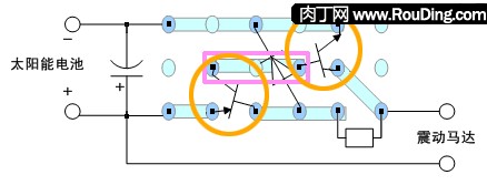
For the circuit diagram of this project (above), we will arrange the actual circuit board corresponding to the position of each component on the diagram (except for external power supply, motor and electrolytic capacitor to facilitate soldering).
This is the “front layout of the board†(the solderless side, the black core blue dot is the solder joint, and the blue strip represents the solder joint):
![[Project] 5.2, PVCRobot [No. 2] mosquitoes in the sun, solar powered robots PVCRobot PVCRobot](http://i.bosscdn.com/blog/f9/73/96/b7dc9b9fa6a816c60acf870eb2.gif)
This is the “floor layout of the board†(the side with solder joints, the black core blue dots for solder joints, and the blue ribbon for solder joints):
![[Project] 5.2, PVCRobot [No. 2] mosquitoes in the sun, solar powered robots PVCRobot PVCRobot](http://i.bosscdn.com/blog/3f/5f/a7/9d2f6e8405e05a9d3315b9691c.gif)
1) Triode We first weld the triode. Insert two transistors on the board according to the “front layout of the board†(do not leave the pins too short, do not let the components too close to the board).
![[Project] 5.2, PVCRobot [No. 2] mosquitoes in the sun, solar powered robots PVCRobot PVCRobot](http://i.bosscdn.com/blog/62/c2/ea/1942b3ab495d94d9ccfc08b3c2.gif)
![[Project] 5.2, PVCRobot [No. 2] mosquitoes in the sun, solar powered robots PVCRobot PVCRobot](http://i.bosscdn.com/blog/12/11/aa/d74b2921dbd6ba6e160aac27b9.jpg)
Here you may ask: "The triode has three pins. How should we identify each pin?" Here I will introduce some methods. Transistor symbol:
The easiest way to determine the pin of a triode is to visually determine its pin through the shape of the triode.
本项目采用的三级管是9014ã€9015两个型å·ï¼Œä¸€èˆ¬è¿™ä¸¤ä¸ªåž‹å·çš„外形å°è£…是TO92(一ç§å°è£…类型,特å¾å°±æ˜¯å¦‚下图的外形),且引脚的排列也是相对固定的。
以上的图示åªæ˜¯TO92å°è£…类型的三æžç®¡é»˜è®¤çš„引脚排列,从本åšå®¢çš„æ·˜å®ç½‘店è´ä¹°çš„套件也是按照这个布局排列。 如果本项目的三æžç®¡å¤§å®¶æ˜¯è‡ªå·±èŽ·å–的而ä¸æ˜¯ç›´æŽ¥ä»Žæœ¬åšå®¢çš„æ·˜å®ç½‘店è´ä¹°çš„套件,或者是说在本项目之外采用其他的三æžç®¡ï¼Œåˆ™å¯èƒ½ç”±äºŽä¸‰æžç®¡çš„外形(å°è£…)ä¸åŒï¼Œæˆ–è€…ç”±äºŽåŽ‚å®¶ä¼—å¤šæ‰§è¡Œçš„æ ‡å‡†ä¹Ÿä¸ä¸€æ ·ï¼Œæ‰€ä»¥å•çº¯ä»Žå¤–形判æ–三æžç®¡çš„引脚并ä¸æ˜¯ç™¾åˆ†ä¹‹ç™¾å‡†ç¡®çš„,这个时候我们就需è¦é€šè¿‡å…¶ä»–更准确的方法去测é‡ã€‚
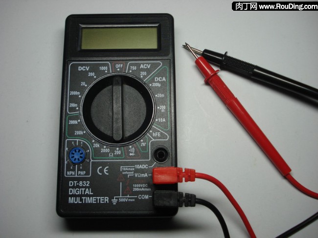
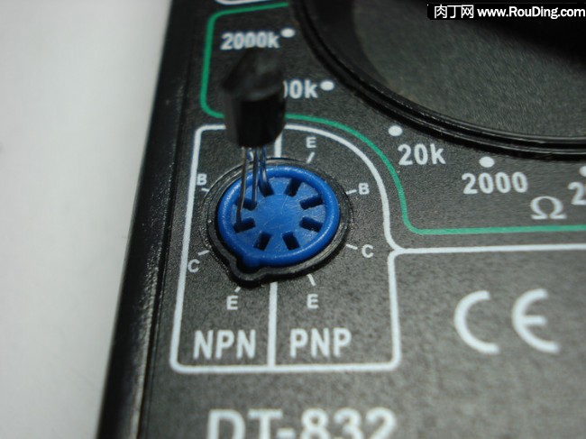
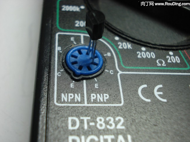
附:如何准确的判别三æžç®¡çš„引脚? è¦å‡†ç¡®åˆ¤æ–三æžç®¡å¼•è„šçš„方法有很多(å¯åœ¨ç™¾åº¦ä¸Šæœç´¢),这里仅æ一个我常用的比较简å•çš„方法——直接用万用表的三级管测é‡åŠŸèƒ½(三æžç®¡ç›´æµæ”¾å¤§ç³»æ•°hFE测é‡)。 我这里以数å—万用表为例进行介ç»ã€‚(关于该款数å—万用表,具体è§ä¹‹å‰çš„工具准备) 把数å—万用表的档ä½è°ƒåˆ°â€œhFEâ€ï¼Œå³æµ‹é‡ä¸‰æžç®¡çš„ç›´æµæ”¾å¤§ç³»æ•°ã€‚
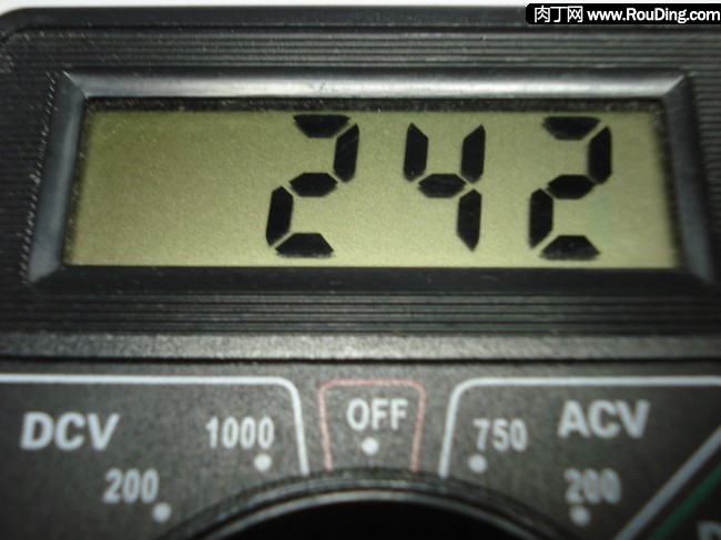
如果测é‡çš„是NPN三æžç®¡ï¼Œåˆ™æŠŠä¸‰æžç®¡æ’到NPN三æžç®¡çš„æ’座上。通常三æžç®¡çš„ä¸é—´å¼•è„šæ˜¯åŸºæž(B),å¯ä»¥å°è¯•å„ç§æ’接方å¼ï¼Œç›´åˆ°æ˜¾ç¤ºå±æ˜¾ç¤ºå‡ºä¸€å®šçš„数值为æ¢(é€šå¸¸æ˜¯å‡ ååˆ°å‡ ç™¾),这个时候三æžç®¡å„引脚的电æžå°±å¯¹åº”æ’å”æ‰€æ ‡æ³¨çš„ç”µæžã€‚
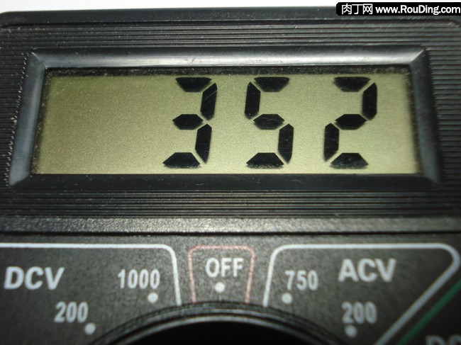
如果测é‡çš„是PNP三æžç®¡ï¼Œåˆ™æŠŠä¸‰æžç®¡æ’到PNP三æžç®¡çš„æ’座上。通常三æžç®¡çš„ä¸é—´å¼•è„šæ˜¯åŸºæž(B),å¯ä»¥å°è¯•å„ç§æ’接方å¼ï¼Œç›´åˆ°æ˜¾ç¤ºå±æ˜¾ç¤ºå‡ºä¸€å®šçš„数值为æ¢(é€šå¸¸æ˜¯å‡ ååˆ°å‡ ç™¾),这个时候三æžç®¡å„引脚的电æžå°±å¯¹åº”æ’å”æ‰€æ ‡æ³¨çš„ç”µæžã€‚
我们把三æžç®¡æŒ‰ç…§æ£ç¡®çš„引脚æ’好,然åŽå°±æŒ‰ç…§â€œç”µè·¯æ¿åº•é¢å¸ƒå±€å›¾â€ç„ŠæŽ¥ä¸‰æžç®¡(紫色部分为连接线)。
焊点之间的连接线,一般我们å¯ä»¥ç›´æŽ¥ç”¨å…ƒä»¶çš„引脚折起æ¥å†ç„Šä¸Šã€‚
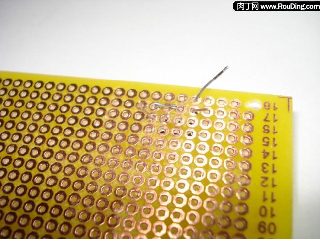
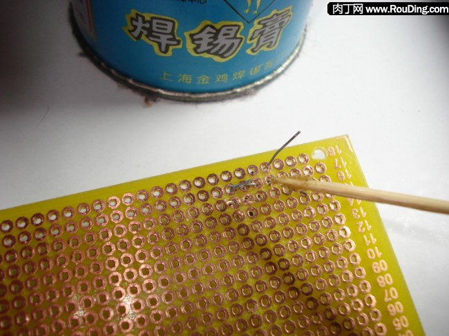
为了焊接时使焊锡更容易粘ä½å¼•è„šå’Œç”µè·¯æ¿çš„铜箔,一般需è¦ç»™ç„ŠæŽ¥çš„部ä½(引脚和铜箔)涂上一点助焊剂åŽå†ç”¨çƒ™é“焊接。
常用的助焊剂主è¦æœ‰æ¾é¦™(用æ¾æ ‘æ ‘è„‚æå–的物质),也有专门焊锡è†(å‰ä¸€ç¯‡å…³äºŽå™¨æå‡†å¤‡çš„æ–‡ç« ä¸æœ‰è¯´æ˜Ž)。值得注æ„的是,比起æ¾é¦™ï¼Œç„Šé”¡è†çš„助焊效果更好,但是焊锡è†ä¸€èˆ¬éƒ½æœ‰ä¸€å®šçš„è…蚀性,对电路æ¿çš„线路有伤害(时间长会è…蚀电路),所以用é‡ä¸å®œè¿‡å¤šï¼Œè€Œä¸”建议焊接好åŽæœ€å¥½ç”¨å¸ƒæˆ–纸擦æ‹å¹²å‡€ã€‚
把元件的引脚按照è¦è¿žæŽ¥ä½ç½®æŠ˜å¥½å¹¶ç”¨å‰ªåˆ€å‰ªæŽ‰å¤šä½™çš„长度,然åŽç”¨ç‰™ç¾æ£’蘸一点焊锡è†æ¶‚在è¦ä¸Šç„Šé”¡çš„引脚和电路æ¿é“œç®”上。
用烙é“粘上焊锡对ç€è¦å¼•è„šå’Œé“œç®”的结åˆéƒ¨ä½è¿›è¡Œç„ŠæŽ¥ã€‚
5V Ac Dc Adapter,Power Adapter 5V,Dc 5V Adapter,5V Ac Adapter
ShenZhen Yinghuiyuan Electronics Co.,Ltd , https://www.yhypoweradapter.com