Because the third generation mobile communication system (3G) still has some shortcomings, including difficulty in achieving a high communication rate, the dynamic range of providing the service rate is not large, and cannot meet various service type requirements, and frequency resources allocated to the 3G system. It has become saturated, and so on, people have proposed the concept of the fourth generation mobile communication system (4G). The key technologies of 4G include:
(1) Modulation and signal transmission techniques (OFDM > OFDM);
(2) Advanced channel coding mode (Turbo code and LDPC);
(3) Multiple access schemes (MC-CDMA and FH-OFCDMA);
(4) Software radio technology;
(5) MIMO and smart antenna technology;
(6) An open structure based on a public IP network.
Research shows that multi-antenna technology can effectively reduce multiple-access interference in 3G based on CDMA technology, and space-time processing can greatly increase the capacity of CDMA system. With its outstanding performance in improving spectrum utilization, MIMO and smart antennas have become hot topics in 4G development.
Smart antenna technology
Smart antennas were originally used in radar, sonar and military communications. The use of smart antennas can meet the quality of service and expand capacity without significantly increasing the complexity of the system.
Smart antennas use digital signal processing technology, using advanced beam switching technology (switchedbeamtechnology) and adaptive spatial digital processing technology (adapTIvespaTIaldigitalprocessing technology) to determine the direction of arrival of useful signals (DOA) by selecting appropriate combining weights to form antennas in this direction. The main beam, while aligning the low gain side lobes or zero sag to the direction of the interfering signal. At the time of transmission, the desired user's received signal power can be maximized while minimizing or even zeroing the interference experienced by undesired users outside the narrow beam illumination range.
The smart antenna introduces a space division multiple access (SDMA) method. In the case of the same time slot, the same frequency or the same address code, the user can still distinguish according to the difference of the signal space propagation path. In practical applications, the antenna array mostly uses a uniform linear array or a uniform circular array. The smart antenna system consists of an antenna array; the beam is formed into a network; and the adaptive algorithm is controlled in three parts (see Figure 1).
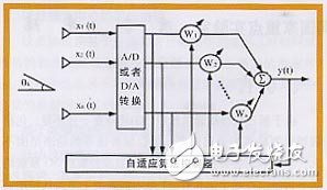
Figure 1 typical smart antenna system
2. Classification of smart antennas Smart antennas are mainly divided into beam-switched smart antennas (switchedbeamantenna) and adaptive array smart antennas (adapTIvearrayantenna).
(1) Beam-switching smart antenna beam-switching Smart antennas have a finite number of fixed, predefined patterns that cover the entire user area with multiple parallel narrow beams (15° to 30° horizontal beamwidth), each beam The orientation is fixed and the beamwidth is also determined by the number of antenna elements (see Figure 2). The beam conversion system is relatively economical. Compared with the adaptive antenna, the structure is simple, no iteration, fast response and good robustness. However, the pre-designed working mode is limited, and the characteristics of the narrow beam will greatly affect the system performance.
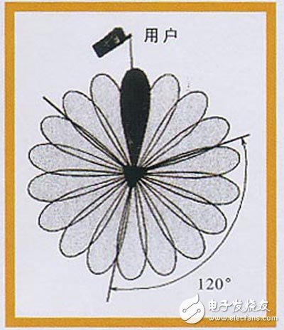
Figure 2 Beam Conversion Smart Antenna
(2) Adaptive array smart antenna
The adaptive array smart antenna estimates the user's direction of arrival (DOA) in real time, forming a main beam in this direction while aligning the side lobes or nulls with the interference direction. The adaptive antenna array generally adopts a 4-16 antenna array structure, and the array element spacing is 1/2 wavelength. If the spacing of the array elements is too large, the correlation between the received signals is reduced. If it is too small, unnecessary grating gratings are formed in the pattern. May amplify noise or interference). Figure 3 compares an adaptive array smart antenna with a beam-switched smart antenna.
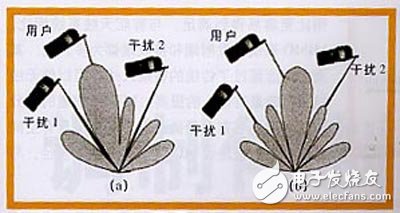
Figure 3 Comparison of adaptive array smart antenna (a) and beam switching smart antenna (b)
The core of smart antenna technology research is adaptive algorithm, which can be divided into blind algorithm, semi-blind algorithm and non-blind algorithm.
The non-blind algorithm needs to use the reference signal to process the received reference signal that is known in advance to determine the channel response, and then determine the weighting values ​​according to certain criteria (such as the zero-forcing criterion), or adaptively adjust according to a certain criterion. Weight (ie the tap coefficient of the algorithm model). Commonly used criteria are minimum mean square error MMSE (Minimummean square error), minimum mean square LMS (Leastmean square) and recursive least squares; and adaptive adjustment takes the optimization method, the most common is the steepest gradient descent method.
The blind algorithm does not need a reference signal or a pilot signal, and it fully utilizes some features (such as constant envelope, subspace, finite symbol set, and cyclostation) inherent in the modulated signal itself, which are independent of specific bearer information bits, to adjust the weight. So that the output error is as small as possible. Common algorithms include constant modulus algorithm CMA (ConstantmodulearithmeTIc), subspace algorithm, decision feedback algorithm and so on.
For non-blind algorithms, relatively blind algorithms usually have smaller errors and faster convergence speeds, but the transmission of reference signals wastes a certain system bandwidth. To this end, a semi-blind algorithm has been developed, that is, the initial weight is determined by the non-blind algorithm, and then the blind algorithm is used for tracking and adjustment.
7.62MM Power+ Signal Power Connector
power connector is used in power module system. It can select the matching power + signal connector according to the need. The feature is that the number of power and signal contacts and the matching sequence can be selected arbitrarily while keeping the connector size and contact core number unchanged.
Plug (male) / socket (female) can be installed at 90 or 180 degrees. It supports mixed or independent combination of signal and power. The quantity range of power and signal is (2-16) pin and (12-128) pin respectively
Product features
High temperature resistant, glass fiber reinforced and flame retardant polyester is used as insulation material
Copper gold composite conductor with high conductivity is used, and the contact area of the conductor is plated with gold
It adopts shrapnel contact, which has the characteristics of integration, small volume, large current carrying capacity, soft plug-in, blind plug-in, self guidance and high dynamic contact reliability. This series of products can be interchanged with FCI's powerblade series and Tyco's multi-beam series
There are three sizes of center distance of power contact: 5.08mm, 6.35mm and 7.62mm
The length of power hole / signal pin can be selected in two sizes. The power rated current is 45A and the signal rated current is 2.5A
7.62MM Power+ Signal Power Connector
ShenZhen Antenk Electronics Co,Ltd , https://www.atkconnectors.com