The factors affecting the operational stability of the single-chip system can be roughly divided into two parts: external cause and internal cause:
1. External factors
Radio frequency interference, which is a conductor (lead or part pin) that is transmitted inside the machine in the form of a space electromagnetic field, which induces corresponding interference, which can be attenuated by electromagnetic shielding and reasonable wiring/device layout;
The interference generated inside the power line or power supply is coupled or directly transmitted through the power line or components in the power supply. This type of interference can be attenuated by means of power supply filtering and isolation.
2. Internal factors
The stability of the oscillation source is mainly determined by the start-up time frequency stability and the duty cycle stability. The start-up time can be affected by the parameter stability of the circuit, which is affected by the parameters such as the temperature and voltage of the oscillator.
Second, the reliability design of the reset circuit
1, the basic reset circuit
The basic function of the reset circuit is to provide a reset signal when the system is powered up, and then cancel the reset signal after the system power supply is stable. For the sake of reliability, after the power supply is stable, the reset signal must be cancelled after a certain delay to prevent the power supply from being turned on.
The vibration caused by the power supply plug split-and-close process affects the reset. The RC reset circuit shown in Figure 1 can achieve the above basic functions, and Figure 3 shows its input-output characteristics. However, problems such as power supply glitch (point A) and slow power supply drop (battery voltage shortage) cannot be solved, and adjusting the RC constant change delay may deteriorate the drive capability. The circuit on the left is a high level reset. The right side is a low level. Sm is a manual reset switch. Ch can avoid the interference of high frequency harmonics on the circuit.
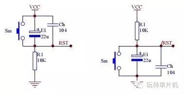
Figure 1 RC reset circuit
The reset circuit shown in Figure 2 adds a diode that quickly discharges the capacitor when the supply voltage drops momentarily. A certain width of the power supply glitch can also reliably reset the system. The lower half of the input and output characteristic diagram of the reset circuit shown in Figure 3 is its characteristic, which can increase the effect of the discharge loop compared with the upper half.
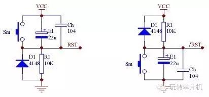
Figure 2 Adding the RC reset circuit of the discharge loop
Using the comparison circuit can not only solve the system instability caused by the power supply glitch, but also reliably reset the power supply slowly. Figure 4 is an example where Q1 cutoff resets the system when VCC x (R1/(R1+R2)) = 0.7V. The amplification of Q1 can also improve the load characteristics of the circuit, but the threshold voltage Vt of the transition is affected by VCC is a prominent shortcoming of the circuit. Using a Zener diode can make Vt basically immune to VCC. See Figure 5. The circuit resets the system when VCC is below Vt (Vz + 0.7V).
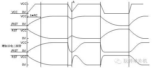
Figure 3 RC reset circuit input-output characteristics

Figure 4 Reset circuit with voltage monitoring function
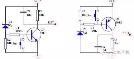
Figure 5 Stable threshold voltage
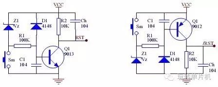
Figure 6 practical reset monitoring circuit
On this basis, the delay capacitor and the discharge diode are added to form a reset circuit with excellent performance, as shown in FIG. 6. Adjusting C1 can adjust the delay time, and adjusting R1 can adjust the load characteristics. As shown in Figure 7, the upper part is the characteristic of the circuit of Figure 5, and the lower part corresponds to Figure 6.
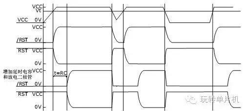
Figure 7 Input-Output Characteristics of Reset Circuit with Voltage Monitoring Function
2, power monitoring circuit
The above reset circuit with voltage monitoring, also called the power monitoring circuit monitoring circuit, must have the following functions:
Power-on reset ensures that the system can be started correctly when power is turned on; power-down reset, when the power supply fails or the voltage drops below a certain voltage value, the system is reset; there are similar integrated products on the market, such as MAX809 produced by PHILIPS Semiconductor Company. , MAX810. These products are small in size, low in power consumption, and have an optional threshold voltage. The system can be reliably reset under different abnormal conditions to prevent the system from running out of control. Rm and Sm in Figure 8 implement manual reset. When this function is not needed, the Reset (or /Reset) terminal can be directly connected to the RST terminal (or /RST terminal) of the microcontroller to minimize the peripheral circuit. PHILIPS Semiconductor can also be selected. Manual reset function for the MAX708.
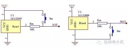
Figure 8 integrated reset monitoring circuit
In addition, the MAX708 can monitor the second power supply signal to provide a warning function for the voltage drop of the processor. With this function, the system can perform certain safety operations, save parameters, send alarm signals or switch backups before the power supply drops to reset. Battery, etc. Figure 9 Application of the meter The MAX708 meter can save the current power to the E2PROM before the power supply glitch or power failure, and save multiple power backup algorithms. This can effectively solve the problem of power loss in the E2PROM. The circuit must select the appropriate warning voltage point to ensure that the VCC voltage drops from the warning voltage to the reset voltage (tB) must be long enough for the power supply of the power supply. The write period of the E2PROM is about 10-20ms. >200ms to ensure stable data writes. Pre-warning voltage adjustment method When VDC is equal to the pre-warning voltage, adjust R1 and R2 so that the voltage of PFI is 1.25V. At this time, /PFO can be detected to confirm whether the internal voltage comparator operates. When adjusting, it must be noted that this comparator is a window comparator. Figure 10 is a program flow chart of the application
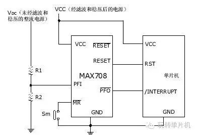
Figure 9 Typical application of the MAX708
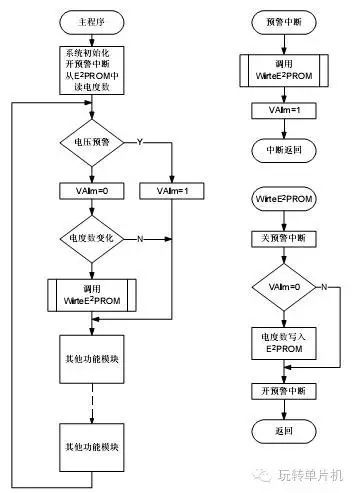
Figure 10. Flowchart of the E2PROM data protection program in the meter application
3. Multi-function power monitoring circuit
In addition to power-on reset and brown-out reset, many supervisory circuits integrate the functions required by the system, such as:
Power supply measurement and control, when the power supply voltage is abnormal, provide early warning indication or interrupt request signal to facilitate the system to achieve abnormal processing; data protection, when the power supply or system works abnormally, necessary protection for data, such as write protection, data backup or switching backup battery The watchdog timer resets the system when the system program "runs away" or "deadlocks"; other functions such as temperature measurement and control, short circuit test, etc.
We call this a multi-function power monitoring circuit. Here are two monitoring circuits that are particularly suitable for use in industrial control, security, and financial industries:
Catalyst's CAT1161 is a 16K-bit E2PROM (I2C interface) with integrated gate, voltage monitoring and reset circuitry. Not only is it highly integrated, it consumes a lot of power (zero power is actually achieved when E2PROM is partially static) and the watchdog is cleared. By changing the level of SDA, the system I/O resources are saved, and the threshold voltage can be modified by the programmer, which covers most applications. The hardware prohibits access to the E2PROM when the power supply drops below the threshold voltage to ensure data security.
Note that the RST is used, the /RST pin is the I/O pin, and the CAT1161 detects that any one of the two pins is abnormal, a reset signal is generated. The pull-down resistor R2 and the pull-up resistor R1 connected to the RST /RST pin must be Connect at the same time, otherwise the CAT1161 will continue to generate reset! Also, the Rm and Sm components can be saved when the manual reset function is not required.

Figure 11. Built-in WDT RESET /RESET E PROM monitor device interface circuit
PHILIPS' SA56600-42 is designed to protect SRAM data in microcomputer systems when the supply voltage is reduced or powered down. When the power supply voltage drops to the normal value of 4.2V, the output CS goes to a logic low level, and CE is also pulled low, thereby inhibiting the operation of the SRAM. At the same time, an active low reset signal is generated for the system. If the power supply voltage continues to drop and reaches the normal value of 3.3V or lower, the SA56600-42 switches the system to operate, switching from the main power supply to the backup lithium battery. When the main power supply returns to normal (the voltage rises to 3.3V or higher), the SRAM power supply will be switched back to the main power supply by the backup lithium battery. When the main power supply rises above the typical value of 4.2V, the output CS becomes a logic high level, making CE Goes high to enable SRAM operation and the reset signal continues until the system resumes normal operation. This device reliably protects the system's data in the SRAM when the system supply voltage is low or suddenly powered down.
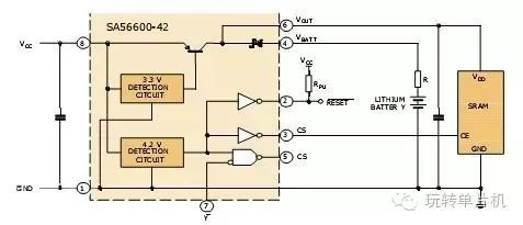
Figure 12. Typical application of the monitoring device SA56600-42 with built-in SRAM data protection circuit
4. Reset circuit design of ARM single chip microcomputer
Whether in mobile phone high-end handheld instruments or embedded systems, 32-bit microcontroller ARM has an increasing share, ARM has become the de facto high-end product industry standard. Due to ARM's high speed, low power consumption and low operating voltage, its low noise margin is a challenge to the limits of digital circuits. It has many aspects such as power supply ripple, transient response performance, clock source stability, and power supply reliability. Higher requirements have also been raised. ARM monitoring technology is complex and very important.
The monitoring circuit realized by discrete components is greatly affected by external influences such as temperature, humidity and pressure, and has inconsistent influence on different components. The board area is too large and too long, and the power consumption is large, which is difficult to accept in many applications. The integrated circuit can solve such problems very well. At present, there are many microprocessors integrated with monitoring circuits, which are in manufacturing cost and process technology. Most of these monitoring circuits are implemented in a low-voltage CMOS process, which is more specialized than a high-voltage, high-linearity bipolar process. There is still a gap in monitoring circuit performance.
The conclusion is that the use of ARM instead of dedicated monitoring circuitry may result in more than gains, and experience has taught us that using dedicated monitoring circuitry can avoid many bizarre problems. ARM application engineers, remember to take less detours!
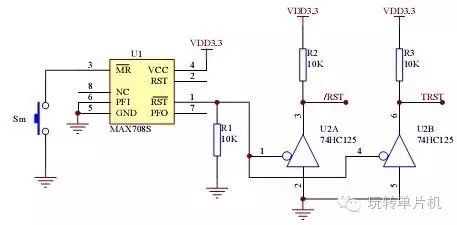
Figure 13. ARM Reset Circuitry with PHILIPS MAX708
Figure 13 shows a practical and reliable ARM reset circuit. The ARM core has a lower operating voltage. R1 guarantees a reliable reset of the operating supply voltage below the MAX708. The TRST signal is used for the JTAG interface. Using the HC125, multiple reset sources can be used to reset the ARM, such as resetting the ARM via the PC serial port or the JTAG interface.
According to ISO 11801 C 2 Edition standards, T568A 568B wiring standars color code schema, communication speed reaches 10G+. it's your best choice to your high quality cabling solution.
Category 6A is one of the latest standards for networking performance approved by the TIA for twisted pair cables. We offer CAT6A Keystone Jack tested for transmission speeds of up to 500 MHz., making them suitable for 10G networks. At higher data speeds, the signal becomes increasingly vulnerable to electromagnetic interference (EMI). To combat this increased vulnerability, many of our CAT6A patch cables feature increased shielding and crosstalk prevention.
The performance of your 10G data network is only as strong as its strongest link. Reinforce your network with our CAT6A kesytone jack. CAT6A exhibits superior crosstalk prevention to handle noise at higher frequencies than CAT6 can handle. Our CAT6A booted Patch Cables have been speed tested to up to 600 MHz.
shielded kesytone jack, category 6a kesytone jack, 10G networking jack
NINGBO UONICORE ELECTRONICS CO., LTD , https://www.uonicore.com