With the rapid development of China's economy, the improvement of residents' living standards and comprehensive quality, the living standards pursued by residents have undergone tremendous changes. The standard of healthy living is the first in living standards, and more and more in China. Residents live in suburbs far from the city to avoid the noisy and polluted environment in the city. In addition, housing prices in urban areas are rising, and there are fewer and fewer people in the city to purchase houses. Therefore, more people choose to live in the suburbs.
Similarly, in order to better and more scientifically accelerate urban construction and reduce urban pollution, many government factories have moved to urban development. At the same time, the country’s key new rural construction supports urban layout adjustment and rural urban construction and rural areas. Urban economic construction. In this way, a living chain is established in the urban areas of small and medium-sized cities, factories around the city, and suburbs (townships). It is the existence of this life chain that makes urban public transportation to the countryside, and it is imperative to realize urban-rural bus integration. This will inevitably lead to some new problems: such as charging problems and standard operation of vehicles.
1 Question raised
1.1 Characteristics of urban and rural smuggling operations There are many differences between urban convenient buses and urban public transportation. As a result, convenient buses cannot be managed in the same way as urban public transportation. The characteristics of urban and rural sedans are: the convenience of ticket sales for passengers; The driving distance of the bus is much larger than that of the city bus; the diversity of the billing standards of the bar, the billing by mileage and the billing by the number of stations; the nature of the operation of the bar is different, and it is contracted to the driver and the car company. Self-operated; the diversity of passengers in the bus and the peak period of the time-sharing; passengers do not follow the principle of first-come, first-serving and so on.
1.2 Problems that occurred After we conducted a survey of China's convenient buses in many provinces and cities, we found that when China's convenient buses are operating, there is a huge difference between the fees paid by the ticket sellers and the actual passengers. The automobile transportation company has done a great job to prevent such incidents. First, the automobile transportation company contracted the convenience bus to the driver. The driver regularly handed over the freight company a certain fee. The result was that the driver rushed for the passengers. Traffic accidents occur frequently. At present, the management of urban and rural toilets operated by this method is the key management of the transportation department. Second, the motor transport company adopts its own operation mode, requiring the ticket seller to give each passenger a ticket, and use the camera video to monitor whether the ticket seller gives each A passenger ticket, the motor transport company calculates the cost based on the ticket stubs submitted by the ticket sales, and watches the real-time video. This method must increase the staff of the motor transport company, and watching the video for a long time will cause psychological and physiological problems for the staff. The damage on it.
To this end, we use single-chip microcomputer and infrared photoelectric technology to realize real-time monitoring of convenient bus operation, including passengers getting on and off the bus, the number of passengers in the car, the running speed of the car, the car stop, the door opening and closing of the car, and providing a serial communication interface. The IC card data reading communication interface, together with the computer background analysis software, will quickly analyze the situation of the car in operation, and manage the passenger riding status information obtained in one day, and give the reference value of the payment fee, and play Supervisory role.
2 The overall design of the system is to achieve the function of automatic monitoring system for convenient bus operation status, improve operational reliability and billing accuracy requirements, and perform statistics and analysis on passengers' access information. The system design generally includes two parts: The operational status automatic monitoring and recording system and the background data processing and analysis system of the PC side. The overall design scheme of the system is shown in Figure 1. 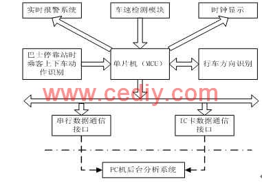
This article refers to the address: http://
Figure 1 Block diagram of the overall design scheme The system is provided to the background data processing and analysis system by means of serial data communication interface and IC card data communication interface. The serial interface is also used to set the license plate number (for the background analysis system to index the data management) and the driving route number, the serial communication baud rate is 19200bps. The data received by the PC background analysis system from the monitoring and recording system includes: the total number of stops at the stop, the total number of people getting on and off, the license plate number, the number of the route number, the number of miles at each stop, and the order of the passengers at each stop. Status, time of each stop and direction code.
3 Automatic monitoring and recording system hardware design Automatic monitoring and recording system hardware consists of six parts: MCU system, power module, vehicle speed detection module, passenger getting on and off motion recognition module, driving direction identification module, clock display module and alarm module.
3.1 Power Module Since the power supply provided by the convenient bus is 24V, and the working voltage of the MCU system is about 5V, we use the DC-DC power supply module PT3104A produced by TI to realize voltage conversion. The input voltage of the module is 18V~40V, output 5V, maximum power. Up to 15W [1].
3.2 Vehicle speed detection module Different types of speed detection methods are different, and the components used for detection are also different. There are two main types: one is a vehicle equipped with a mechanical odometer, and the other is an electronic speedometer. vehicle. The former one has no electric pulse speed signal output, and needs to be equipped with a vehicle speed sensor. Generally, a Hall speed sensor is used, and the latter can directly take a signal from the digital signal input end of the speedometer. These two connection methods are shown in Figure 2 and Figure 3. 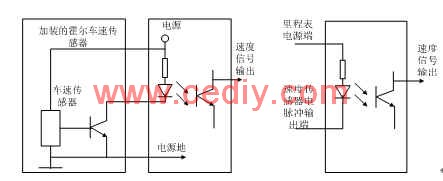
Figure 2 Schematic diagram of the speed detection connection of the mechanical odometer. Figure 3 The speed detection connection diagram of the electronic speedometer is to be noted that the power supply of Figure 2 is provided by the automatic monitoring recorder, while the power supply of Figure 3 is powered by the electronic odometer. provide.
3.3 The movement recognition module of the passenger getting on and off the vehicle is recognized by the infrared photoelectric switch. Due to the characteristics of the convenient bus itself, the time difference between the passengers getting on and off the vehicle and the time of completing the action, the irregularities of the carried items may cause the action. Misidentification. Therefore, there are some specific requirements for infrared photoelectric switches: reaction speed, anti-vehicle vibration interference, light control range, angular size and installation position on the vehicle.
Two pairs of PNP photoelectric switches are installed in the front and rear doors. One is required to be normally open, one is normally closed, the working voltage is 24V, the operating time is <=2ms, the detection distance is 60~80cm, and the two are installed on the same horizontal line, the spacing is k. Control within 10 ~ 15cm (to reduce the misidentification of other objects), as shown in Figure 4. 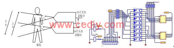
Figure 4 Photoelectric switch installation diagram Figure 5 System and peripheral detection device connection schematic diagram Assume that 1# photoelectric switch is normally open (no action output state is 1), 2# is normally closed (no action output state is 0), passengers are on The state of the car is: 10 (initial state), 00, 01, 11, 10 (return to the initial state), and the state of getting off is: 10 (initial state), 11, 01, 00, 10 (return) Initial state). The obtained passengers' getting on and off order, the stop time and the total number of people getting on and off the station are recorded in the NVRAM-DS1235Y memory extended by the MCU system, and are stored in binary for data statistics of the background analysis software.
3.4 Driving direction identification module The driving direction identification module is mainly used to identify whether the vehicle departs from the starting station or the terminal station, mainly considering different charging modes in different directions. The module is mainly implemented by DF wireless transceiver module. It is realized by SC2262 and SC2272 encoding and decoding chips. The transmitting module is installed at the inbound or outbound port. The receiving module is installed at the monitoring and recording system and receives the signal to the MCU system.
3.5 Clock and Display Module The convenient bus stop time is provided by the module. It is realized by the power-down protection calendar clock chip DS12887. The chip is 24-pin, with clock, alarm clock and calendar function up to 2100. 12-hour or 24-hour timekeeping, with AM and PM, week and leap year automatic compensation function [2][3]. The display module is used to display the current time and current car driving status, and is implemented using LCD12864.
Part of the circuit schematic diagram of the whole monitoring and recording system and photoelectric switch and switch door detection is shown in Figure 5. K1 and K2 are used to detect the relay of the door switch. The relay power supply is powered by the car 24V power supply, 4 optical isolation couplings are used to receive 4 photoelectric switch signals of the front and rear doors, 2 are used to receive the door switch signal, and 1 is used for receiving. The vehicle speed pulse signal is reserved for use. Each of the acquired signals is sent to the SN74HC244 for latching, and the MCU system obtains a real-time signal from the read 244.
4 software design
The core device of the MCU system uses the SST89C58, which has a watchdog function timer [4]. The development environment uses KeilC51, which has powerful pointer functions and subroutine design features, which shortens the overall design cycle. Figures 6 and 7 show the entire workflow and serial interrupt processing flow of the system. The data communication with the PC background data statistical analysis system uses serial communication and IC card (currently reserved).
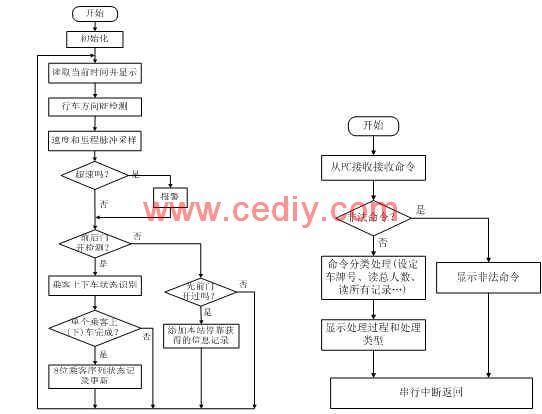
Figure 6 System total program flow chart Figure 7 Serial interrupt processing flow chart before and after the door open detection is basically similar, the following program is the front door open no detection program:
Void Forward_Door_Check(void)
{ if(FORWARD_DOOR == OPEN) // Door open detection { if(Forward_Door_Opened == FALSE)
{ Delay_500Ms();
If(FORWARD_DOOR == OPEN)
Forward_Door_Opened = TRUE;
}
}
Else // gate detection { if(Forward_Door_Opened == TRUE)
{ Delay_500Ms();
If(FORWARD_DOOR == CLOSE)
Forward_Door_Opened = FALSE;
}
}
}
When the convenient bus stops at the station and starts driving again, it is necessary to add the stop information (stop time, mileage and passenger access information) to the external extended NVRAM-DS1235Y data record. The procedure is as follows:
Void ThisStation_Update(void)
{ byte xdata *ptr0;
Ptr0 = START_ADDRESS + Total_Record_Length; // Add the starting address of the record
*ptr0++ = Mileage >>8; // MSB mileage
*ptr0++ = Mileage; // LSB mileage
*ptr0++ = UpDown_Number_This_Station; // Total number of people getting on and off the station......... // Stop station time update
Total_Record_Length=Total_Record_Length+RECORD_HEAD_LENGTH+ UpDown_Number_This_Station/8;
If((UpDown_Number_This_Station%8)!=0)
Total_Record_Length++;
UpDown_Number_This_Station = 0;
Current_Stop_Times = Current_Stop_Times+1;
Mileage = 0;
}
5 Conclusion This system uses SST89C58 single-chip microcomputer, photoelectric switch, wireless transceiver module to develop a convenient bus operation status automatic monitoring system, including the speed of the vehicle, mileage, passengers get on and off the motion recognition, and use the serial port to communicate with the PC, with Background analysis software for data statistics. Through actual on-board experiments, the statistical data is highly accurate.
The author of this paper is to use the photoelectric switch to solve the passenger's motion recognition, and use the wireless transceiver module to solve the vehicle travel route identification, which plays an important role in vehicle operation management and passenger billing management.
portable charging power station 80000 mAh Portable Power Station portable power station 300w
with LED Light 1000W Digital Display Multifunctional Portable Power Station Fast Charging Power Bank
Portable Power station 800W 1000W 5000W
Boluo Xurong Electronics Co., Ltd. , https://www.greenleaf-pc.com