UAV flight control and airborne electronic equipment control commands are mainly generated by software in the ground control computer or UAV controller. These two independent control methods are mutually backup. The UAV controller is mainly designed and implemented by hardware circuits and embedded software, and does not depend on the computer, so it has the advantages of high reliability and good stability. It is one of the main ways to realize remote control of UAVs. The traditional UAV controller is mainly designed and implemented by chips such as single chip microcomputer, ARM and 8279, which has the advantages of simple system structure and so on.
The system has requirements on command delay and timing synchronization of the measurement and control system. This design method increases the design complexity of the measurement and control equipment software, especially for the practical application requirements of low-latency data transmission on the remote control channel of the UAV UAV, traditional The command delay generated by the UAV controller is difficult to meet the UAV takeoff and landing control requirements.
The UAV controller based on FPGA design takes full advantage of the parallel data processing capabilities and synchronous design advantages of FPGA, and integrates the functional modules such as keyboard scanning, command encoding and display, and asynchronous serial transmission of commands into the FPGA, and the peripheral circuits are only Contains simple circuits such as AD sampling, level conversion and driver chips, avoiding the timing shortcomings of single-instruction cycle chips such as MCUs. The hardware structure of the system is simpler and more scalable. The triggering of remote control commands to the output of the command data group delay The time is less than 80 ms, which can meet the real-time remote control requirements of various types of drones.
1 System hardware designUAV controller is mainly composed of control keyboard, digital display board and controller data processing board. The control keyboard is composed of an 8x8 switch matrix keyboard and a heading controller, which mainly realizes the generation of the scan code of the UAV controller keyboard and the heading analog quantity. The digital display board is composed of 6 hexadecimal digital tubes, which mainly realize the synchronous display of control instruction codes and course data. As the core component of the UAV remote controller, the controller data processing board uses Altera's low-cost Cyclone4 series FPGA chip EP4CE10 as the core chip for command and data processing; in order to reduce FPGA hardware resource consumption, the AD chip uses MAXIM's serial The 12Bits AD sampling chip MAX11105, the theoretical heading sensor control accuracy can reach 0.09 °; the UART level conversion chip is designed and implemented using MAXIM's MAX3387 chip, which has good scalability. The controller signal processing board mainly implements functions such as keyboard scanning and AD sampling, command coding and display, and asynchronous serial transmission of remote control commands for UAV control commands. The block diagram of the system hardware structure is shown in Figure 1.
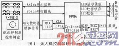
As shown in Figure 1, the FPGA on the controller data processing board performs row and column scanning and AD sampling on the 8x8 matrix keyboard and the heading controller analog signal on the control keyboard to obtain the keyboard scan code and heading analog data, and collects The received commands and data are encoded and converted to obtain command control codes and heading control data. FPGA divides the coded data into two channels at the same time, one channel drives the digital display panel for real-time display, and the other channel performs remote control framing to send to the MAX3387 according to standard asynchronous serial communication protocol (UART) for RS232 level conversion. The asynchronous serial remote control data of the command is sent to the drone through the measurement and control equipment to realize the remote control function of the drone.
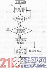
2 System software designThe software of the UAV controller is integrated in the FPGA, programmed in VHDL language, and compiled and online simulated in the QuartusII software environment of Altera Corporation. The controller mainly includes function modules such as keyboard scanning, command coding and display, and asynchronous serial sending of commands. The signal flow of the system is shown in Figure 2. After the system is powered on, the FPGA scans the control keyboard and heading controller every 40 ms and collects AD data. When it is detected that a control key is triggered, the key debounce recognition program is started to effectively control the key keyboard. The scan code and AD collected data are converted into control command code and heading control data, and the command and data are divided into the same two ways, one way is sent to the LED driver module to generate a hexadecimal digital tube display drive signal, and the other way is sent to the command asynchronous serial The sending module carries out remote control framing and control data loading, and finally sends the remote control frame data containing command data according to the asynchronous serial data communication protocol (UART).
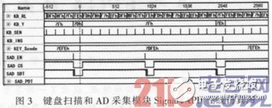
According to the real-time requirements of the control instructions, the system design performs row and column scanning and AD sampling on the matrix keyboard and the course controller every 40 ms. When the keys on the keyboard are triggered, the key debounce recognition program is started and the output meets the response time. Required keys 16 bits keyboard scan code. At the same time, the analog serial data of the heading controller collected by AD is serial-to-parallel converted to output 12 bits of parallel heading control data. The SignalTapII online simulation results of this module are shown in Figure 3. KB_RL and KB_Y are row scan lines and column scan lines respectively, KB_SEN is the keyboard scan enable signal, KEY_SCode is the keyboard scan code output after the key is triggered, SAD_CS is the chip enable signal, SAD_SDT is the chip serial data input, SAD_PDT The result data of the heading controller after serial-to-parallel conversion. It can be seen from Figure 3 that a total of 2 control buttons are triggered in sequence, and a total of 2 keyboard scan codes are output: 7DFE and 7EFE. The heading controller outputs 2EB of data, and the corresponding heading control angle value is about 66 °.
The instruction encoding and display module encodes the received 16-bit keyboard scan code and 12-bit heading controller data according to the data transmission protocol, and sends the encoded control instructions and data to the instruction sending module. At the same time, To ensure the correct transmission of command codes and heading controller data, the module drives 6 hexadecimal digital display tubes to display the encoded command data and heading controller data in real time. The signalTapII online simulation results of the instruction encoding and display module and the display results of the digital tube are shown in Figure 4. KB_INS is the instruction valid flag, KB_EDAT is the encoded instruction code, and SAD_EDT is the encoded angle value. LED_LE is the nixie tube data latch signal, LED_BL is the nixie tube enable signal, LED_DL is the nixie tube data input terminal, as can be seen from FIG. 4, the encoded control command code and the heading controller angle are 033H and 66 °, nixie tube The displayed results are 033 and 066.
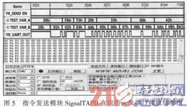
2. 3 instruction sending moduleAfter the command sending module receives the encoded control command and the heading controller data, it converts the encoded command data into remote control frame data, and outputs the remote control frame data to the MAX3387 according to the asynchronous serial communication protocol (UART) for level conversion The serial baud rate of the remote control frame data is selected from 19 200, 8 data bits, 1 start bit, 1 stop bit, and no parity bit. The instruction simulation module SignalTapII online simulation results and the remote control frame data results received by the computer are shown in Figure 5. YK_SEND_EN is the data transmission enable signal, Test_Vara is the 8-bit parallel remote control data sent, and YK_UART_Out is the asynchronous serial data FPGA output waveform signal.
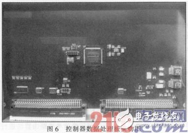
The UAV controller is installed in a certain UAV ground control station. After the ground station is powered on, the controller data processing board starts to work, and the keyboard scan and AD sampling of the 8x8 matrix keyboard and UAV heading controller are performed at 40 ms intervals, and the collected data is converted into the corresponding remote control command code in real time. , All the way to drive the digital display tube to display the instruction code in real time, all the way to convert the instruction code into RS232 asynchronous serial data and send it to the UAV through the measurement and control equipment, the controller data processing board is shown in Figure 6. The actual application results show that the technical indicators of the UAV controller based on FPGA design meet the requirements of use, the control command group delay is less than 80 ms, and the equipment operates stably and reliably.
According to the control characteristics of drones, a design scheme of UAV controller based on FPGA is proposed in this paper. This method makes full use of FPGA parallel processing capability, simplifies the hardware structure of UAV controller, and reduces the group delay of remote control commands. At that time, the timing matching problem of the measurement and control equipment was solved, and it has good function scalability. The controller has been successfully applied in a certain type of UAV system.
In addition to CWDM, DWDM, FWDM, LAN WDM, FBT WDM, AAWG WDM, there are other WDM realted equipment that commonly used together to form up passive optical network. Like Mechanical Fiber Optic Switch, WDM PD, Pigtail PD, TAP WDM Devices, Optical Isolator, Optical Circulator, etc. In other words, Mechanical Fiber Optic Switch, WDM PD, Pigtail PD, TAP WDM Devices, Optical Isolator, Optical Circulator, etc., are the most commonly used WDM related equipment in construction of optical network. They all play important roles when setting up a integrated fiber optical network. You can always trust GL-COM in this area.

Mechanical Optical Switch is based on Advanced Optoelectronic Integrated Technology. it connects optical channels by redirecting an incoming optical signal into a selected output fiber. This is achieved using a Opto-Mechanical proprietary configuration and activated via an electrical control signal. Mechanical Fiber Optic Switch connects optical channels by redirecting an incoming optical signal into a selected output fiber. The mechanical operation offers ultra-high reliability and fast switching speed as well as bi-directional performance.
WDM Related Equipment, Mechanical Fiber Optic Switch, WDM PD, Pigtail Fiber Cable, TAP WDM Devices, Optical Isolator, Optical Circulator
Shenzhen GL-COM Technology CO.,LTD. , https://www.szglcom.com