Wind turbines are diverse, but they can be divided into two categories:
1. The horizontal axis wind turbine, that is, the rotating shaft of the wind wheel is parallel to the wind direction;
2. The vertical axis wind turbine, that is, the rotating shaft of the wind wheel is perpendicular to the ground or the direction of the air flow.
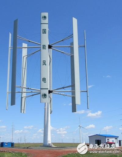
Vertical axis wind turbine
This article mainly describes the vertical axis wind turbine. The vertical axis wind turbine (VAWT) is mainly classified into a resistance type and a lift type.
The resistance type vertical axis wind turbine mainly uses the resistance generated by the air flowing through the blade as the driving force, and the lift type uses the lift generated by the air flowing through the blade as the driving force. As the blade rotates, the resistance decreases sharply with the increase of the rotational speed, and the lift increases instead. Therefore, the efficiency of the lift-type vertical-axis wind turbine is much higher than that of the resistance type.
There are several types of vertical-axis wind turbines that use resistance rotation, among which are wind turbines made of flat plates and cups, which are pure resistance devices; S-type windmills with partial lift, but mainly resistance devices. These devices have a large starting torque, but have a low tip speed ratio and provide a low power output with a certain size, weight and cost of the rotor.
The Dalier wind wheel was invented by the French GJM Darieu in the 1930s. In the 1970s, the Canadian National Academy of Sciences conducted extensive research on this and was the main competitor of horizontal-axis wind turbines. The Darryl type wind wheel is a lifting device. The curved blade has a profile of airfoil. It has a low starting torque, but the tip speed ratio can be high. It has a high power output for a given wind wheel weight and cost. . There are many types of Darrying wind turbines in the world, such as Φ type, Δ type, Y type and H type. These wind wheels can be designed as single, double, triple or multi-blade.
It has been more than 180 years since Darrier invented the lift-type vertical-axis wind turbine, but it has not been widely used, mainly because its own shortcomings hinder the application. The failure to self-start is an important shortcoming, but the main disadvantage is that the range of variation of the wind and the range of the load are too narrow, which also involves the disadvantage that it cannot be adjusted.
1. Fixed blade lift type vertical axis wind turbine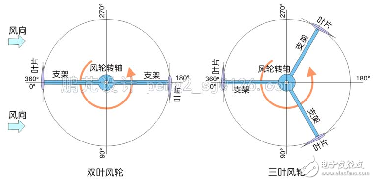
Fig.1 Wind turbine blade layout diagram of lift vertical axis wind turbine
The traditional Dalier wind turbine adopts a Ñ„-shaped blade, and currently more straight blade (H-type) structure is adopted. The blade of the Dalier wind turbine is fixed relative to the wind wheel, that is, the blade chord angle is not adjustable. Figure 1 is a diagram of the blade distribution of the wind wheel.
The lift type wind turbine uses the lift of the blade to push the wind wheel to rotate. For most common airfoil blades, under ideal conditions, the angle of attack can generate lift at 0 to 15 degrees, and at 8 to 13 degrees, it can generate large lift. And the resistance is small. Fig. 2 is a diagram showing the flow of air and force when the blades of the wind turbine are rotated to the wind side (0 degree position).
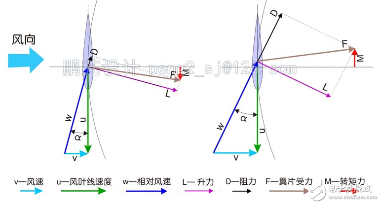
Figure 2 Comparison of lift resistance of blades in normal and stall
In the left diagram of Fig. 2, the blade is subjected to the relative wind speed W to generate the lift L and the resistance D. The angle between the relative wind speed W and the blade string, that is, the angle of attack α of the blade is about 14 degrees, and the relative wind speed W is the wind speed V and the blade motion. The velocity u is synthesized, and the speed of the blade motion at this time is about 4 times the wind speed, that is, the tip speed ratio is 4. The resultant force of the lift L and the resistance D is F, and the moment force of the force on the wind wheel is M, which is a force that pushes the wind wheel to rotate. When the tip speed ratio is 4, the blade can generate a moment that pushes the rotation of the wind wheel on either the wind side or the leeward side. The lift is small only on both sides (90 degrees and 180 degrees), and there is little negative To the moment.
In the right side view of Figure 2, the wind speed doubles, the speed of the blade motion does not change, the tip speed ratio is about 2, the blade's angle of attack α is about 27 degrees, and the blade works in a stall state, at which time the blade produces lift. L decreases, the resistance D rises greatly, and the moment force M generated by the wind wheel is negative, which prevents the rotor from rotating. The possibility of the blade generating a negative moment at this wind speed and speed is very large.
In fact, when the blade tip speed ratio is 4 (α is 14 degrees), it is already at the edge of the stall. When it is lower than 4, the lift L is no longer increased, the resistance D has risen significantly, and the moment force M generated by the blade is likely to be 0. Or negative. Fortunately, when the blade is running in the middle of the range of 0 to 90 degrees, the blade has a small angle of attack and can generate a positive moment. There is also such a region in the middle of 90 to 180 degrees, 180 to 270 degrees, and 270 to 360 degrees. However, when the tip speed ratio is less than 3.5 (α is greater than 16 degrees), the area is getting smaller and smaller.
Figure 3 is the relationship between the power factor Cp of the lift vertical axis wind turbine and the tip speed ratio tsr. It can be seen that the tip speed ratio is between 4 and 6 and the airflow is in an ideal state. under.
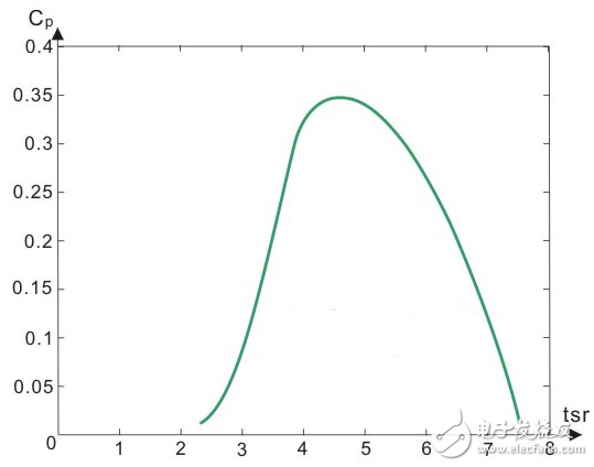
Fig. 3 is a graph showing the relationship between the power coefficient of the fixed-blade vertical axis wind turbine and the tip speed ratio
However, the wind power cannot be stabilized, and the wind turbine load will not change. When the wind speed increases rapidly, the wind turbine speed cannot be synchronized immediately, the tip speed ratio may fall below 3.5, and the wind turbine may suffer from the reverse torque. Unstable operation; this situation also occurs when the wind turbine load increases and the speed decreases to the tip speed ratio. The wind turbine will drop faster due to the load speed when the wind speed drops. This may also occur. Requiring a narrow range of wind or load variation is a major problem for fixed-blade lift-type vertical-axis wind turbines. The inability to self-start is also an important drawback of fixed-blade lift-type vertical-axis wind turbines, which imposes many limitations on applications.
High Voltage Industrial High Bay Driver UFO
Fahold LTD -- Products Dept. has introduced a new series of 200-480V LED Round drivers, available in 100W,150W and 240W outputs.
Each model includes input voltage ranges from 200Vac to 480Vac. The FD-150GW constant current driver offers fixed and dimmable output models. Some models are Class 2 rated.
All models feature Metal housings and are IP65 rated--making them suitable for applications subject to moisture. They offer over-voltage, over-current and short circuit protection with automatic recovery to keep luminaires performing. it has the special heat dissipation design, wehich allow to work at Ta 65°C. The drivers are UL Recognized for both US and Canada, and are CE certified.

Industrial Lighting Led Driver,480V Constant Led Driver Circuit,UFO High Bay Lighting,Led Driver Power
ShenZhen Fahold Electronic Limited , https://www.fahold.net