As mentioned in the previous article, each PCIe device can have only one function, Fun0. It can also have up to 8 functions, namely Multi-Fun. Regardless of how many features this PCIe device has, each function has a unique configuration space.
Like the PCI bus, each function in the PCIe bus has a unique identifier that corresponds to it. This identifier is BDF (Bus, Device, Function). The PCIe configuration software (ie, the root application layer, typically a PC) should be able to recognize the topology logic of the entire PCIe bus system and each bus within it. Each device and each function.
In the BDF, the Bus Number occupies 8 bits, the Device Number occupies 5 bits, and the Function Number occupies 3 bits. Obviously, the PCIe bus supports up to 256 sub-buses. Each sub-bus supports up to 32 devices. Each device supports up to 8 functions.
The PCIe bus uses a depth first search (Depth First Search) topology, and Bus0 is always assigned to the Root Complex. The root contains an integrated Endpoint and multiple ports. Each port has a virtual PCI-to-PCI bridge (P2P) inside, and this bridge should also have a device number and function number.
It should be noted that each device must have function 0 (Fun0), and the other 7 functions (Fun1~Fun7) are optional.
A simple example is shown below:
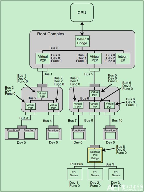
Note: The topology logic for the PCIe bus will be described in detail in a later article.
The previous article on the PCI bus introduced the configuration space of the PCI bus. In order to be compatible with these PCI devices, the PCIe bus almost completely reserved the configuration space of the PCI bus. The configuration space is expanded to 4KB to support new functions in some PCIe buses, such as PCI Express Capability, Power Management and MSI/MSI-X.
The following figure shows the configuration space inherited from the PCI bus:
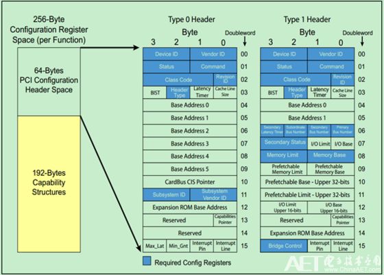
The following figure shows the PCIe new configuration space:

Usb Cables,Usb Wires,Usb Wire,Micro Usb Cable
UCOAX , https://www.jsucoax.com