The principle of computer ATX auxiliary power supply circuit and maintenance of ATX switching power supply, auxiliary power supply circuit is the key to maintain the normal operation of microcomputer and ATX power supply.
First, the auxiliary power supply outputs a +5VSB standby voltage to the power supply monitoring circuit of the microcomputer motherboard.
Second, it supplies about +22V DC working voltage to the internal pulse width modulation chip of the ATX power supply and the primary winding of the push transformer. As long as the ATX switching power supply is connected to the mains, no matter whether the microcomputer is started or not, other circuits can have the rotation of standby control and controlled start, and the auxiliary power supply circuit is in the high frequency, high voltage self-oscillation or controlled oscillation. The working state, part of the circuit itself lacks perfect voltage regulation and overcurrent protection, making it the highest failure rate in the ATX power supply. In this paper, the three domestic ATX switching power supplies used in the current microcomputer are taken as an example. According to the auxiliary power supply circuit of physical mapping, the working principle of the auxiliary circuit is analyzed as follows:
First, the Galaxy Silver Star-280B ATX power supply auxiliary circuit (see Figure 1)
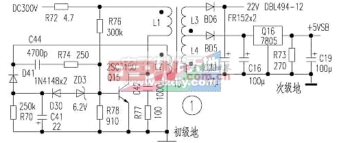
The rectified 300V DC voltage is driven by the current limiting resistor R72 and the starting resistors R76 and T3 to respectively add the primary winding L1 of the transformer to the b15 poles of the Q15 oscillation tube, and the Q15 is turned on. The feedback winding L2 induces a potential, which is applied to the Q15b pole through positive feedback loops C44 and R74 to accelerate Q15 conduction. The T3 secondary windings L3 and L4 are negatively positive at the induced potential, and the rectifiers BD5 and BD6 are turned off. As the C44 charging voltage rises, the base current injected into Q15 becomes less and less, Q15 exits saturation and enters the amplification state, and the oscillating current of the L1 winding decreases. Since the current in the inductor coil cannot jump, the L1 winding induces a potential inverse. Phase, the inverting induced potential of the L2 winding is charged to C41 through the R70, C41, D41 loops, the positive pole of C41 is grounded, and the negative pole is negatively charged, so that ZD3 and D30 are turned on, the base of Q15 is quickly pulled to the negative potential, and Q15 is cut off. T3 secondary winding L3, L4 induced potential is negative, BD5, BD6 rectifier diode output two DC power supply, of which +5VSB is the operating voltage of the host wake-up ATX power controlled start, if the voltage is abnormal, when using the keyboard, mouse When the network remote mode is turned on or the chassis panel start button is pressed, the ATX power supply cannot be controlled to start outputting multiple DC stabilized power supplies. During the cut-off period, the C44 voltage is discharged through the windings of R74 and L2. As the discharge voltage of C44 decreases, the base potential of Q15 rises. Once it is greater than 0.7V, Q15 turns on again. During the conduction period, C41 is discharged through R70. If the time constant of the C41 discharge loop is much longer than the oscillation period of Q15, the forward voltage of 0.7V is finally formed at the base of Q15, and the potential of the negative bias is reversely turned off to reduce the Q15 turn-off loss. D30 and ZD3 form a base negative bias cut-off circuit. R77 and C42 are resistance-capacitance absorption circuits that suppress the peak resonance pulse generated by the collector when the absorption of Q15 is off.
The auxiliary power supply does not have any controlled adjustment voltage protection circuit. The common fault is that the resistance of R72 and R76 becomes larger or open circuit, and the breakdown of Q15, ZD3, D30 and D41 is short-circuited, and the rectifier tube breakdown in the AC input rectifier filter circuit is accompanied. , exchange insurance burst phenomenon. The concealed fault is that the C41 is close to the Q15 heat sink and is heated and baked, and the capacity is reduced. As a result, the rectified output voltage of the secondary winding BD6 rises sharply when the ATX power supply is connected to the mains, up to 80V, and the DBL494 pulse width modulation chip is often burnt out at the moment of power-on. This kind of fault is quite hidden, and the amateur overhaul is generally not easy to detect, resulting in a considerable part of the repaired Galaxy ATX switching power supply failed to find the root cause of the fault, and thus burned the newly replaced components.
Second, Senda Power98 ATX power supply auxiliary circuit (see Figure 2)
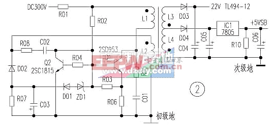
The self-oscillation operation works in the same way as the Galaxy ATX switching power supply. An overcurrent regulating tube Q2 is added to the T3 driving transformer primary winding oscillating circuit. Q1 self-oscillation is regulated by Q2. When the rectified input voltage of T3 primary winding rises or the secondary winding load is too heavy, the oscillating current flowing through L1 winding and Q1 c and e pole increases, the voltage drop of R06 overcurrent detection resistor rises. It is transmitted from R03 and R04 to Q2 b pole. The potential of Q2 b is greater than 0.7V. Q2 is turned on, the base potential of Q1 is pulled low, the saturation conduction time of Q1 is shortened, and the energy storage of primary winding from electric energy to magnetic energy is reduced. The secondary winding rectified output voltage drops. When the self-excited oscillation of the Q1 oscillation switch tube is normal, the Q2 adjustment tube is turned off.
The circuit improves the reliability of the auxiliary power supply to a certain extent, but when the commercial power rises, the rectified input voltage rises, or the T3 secondary winding load is too heavy, and when the Q2 adjustment action lags, the R01, R02, Q1 will still be burned. R06 components, sometimes with ZD1, D01, Q2 components. Third, the technology exhibition 200XA ATX power supply auxiliary circuit (see Figure 3)
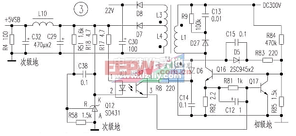
The primary winding side is the same as the above two circuits; the secondary winding side adds an overvoltage protection circuit.
The working principle is as follows: If the output voltage of the secondary winding of T3 rises, the voltage is divided by R51 and R58. The potential of the Q12 reference terminal of the precision voltage regulator is increased, the potential of the Uk of the control terminal is lowered, the LED of the IC1 is turned on, and the phototransistor c and e poles are turned. The output current flows into the base of the adjustment tube Q17, and the Q17 is turned on to turn off the oscillation switch tube Q16, thereby providing overvoltage protection. D27, R9 and C13 form the Q16 peak resonance pulse absorption loop, and C29, L10 and C32 form a filter loop to eliminate the ripple voltage of +5VSB.
Pvc Junction Box,Cable Junction Box,Plastic Junction Box,Electrical Junction Box
FOSHAN SHUNDE LANGLI HARDWARE ELECTRICAL CO.LTD , https://www.langliplastic.com