The detector can respond to alarms in the supply voltage fluctuations of the circuit under test. This unobservable fluctuation is often not allowed for some systems, it can create logic errors or cause significant damage.
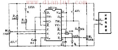
As shown in the figure, the circuit is mainly composed of a 5G7556 dual timer, the left half of which constitutes the power supply falling wave detection circuit, and the right half constitutes the power supply rising wave detecting circuit. The working power is taken directly from the circuit under test, which is also the object of monitoring.
When the power supply voltage fluctuates, the reset threshold voltage of the 7556 also falls. When the threshold is lower than the voltage saved on C1, F1 is reset to a low level, and LED1 emits an indication.
When the power supply voltage rises and falls, the trigger set voltage of the 7556 also rises. When the trigger voltage rises above the saved voltage value on C2, F2 is set to output high level, and LED2 illuminates to indicate an alarm. Once LED1 and LED2 are illuminated, they can only be extinguished by pressing switches AN1 and AN2.

About this item
- 9V Switching wall charger
- 110V input voltage / 9VDC 1A/2A/3A... output voltage
- For use with Arduino Uno, Mega and MB102 Power supply boards
- Connector size: 5.5 x 2.1mm/5.5*2.5mm...
- Center or Tip is positive, sleeve is negative
9v wall charger,AC Power Supply Wall Plug,Wall Adapter Power Supply,9V Power Adapter,ac 50/60hz power adapter,Wall Adapter Power Supply - 9VDC,100-240v converter switching power adapter
Shenzhen Waweis Technology Co., Ltd. , https://www.huaweishiadapter.com