The RX3i's power modules are as simple as I/O modules plugged into the backplane and work with any standard RX3iCPU. Each power module has an automatic voltage adaptation function that allows the user to select different input voltages without jumpers. The power module has a current limiting function. When a short circuit occurs, the power module automatically shuts down to avoid hardware damage. The RX3i power module is tightly integrated with CPU performance for stand-alone control, fail-safe and fault tolerance. Other performance and safety features include advanced diagnostics and built-in smart switch fuses.
The input voltage of the RX3i's power module can be 100~240VAC, 125VDC, 24VDC or 12VDC. The model and performance parameters of the RX3i power module are shown in Table 1-3. In the power module, except for the IC695PSD040 module, which requires one slot, the other power modules need to occupy two slots. The Universal Power Module (IC695) is mounted on a universal backplane. Except for the highest numbered (rightmost) slot, the expansion power module (IC694) must be installed in the leftmost power socket on the expansion backplane.
The appearance of the power module IC695PSD040 and IC695PSA040 is shown below.
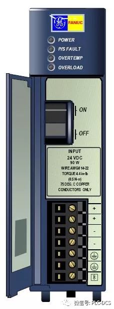
Appearance of IC695PSD040
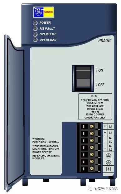
Appearance of IC695PSA040
Take the IC695PSD040 power module as an example. The input voltage range of the module is 18~39VDC, and the output voltage is 24 VDC, which provides 40W output power. The function of the four LEDs on the power module is as follows:
1. POWER-Power (green/amber). When the LED is green, it means that the power module is supplying power to the backplane. When the LED is amber, it means that the power has been applied to the power module, but the switch on the power module is off.
2.P/S FAULT-Fault (red). When the LED is lit, it means that the power module is faulty and does not provide enough voltage for the backplane.
3. OVERTEMP - The temperature is too high (amber yellow). When the LED is lit, it means that the power module is approaching or exceeding the maximum operating temperature.
4. Overload (amber yellow). When the LED is lit, it means that at least one output of the power module is close to or exceeds the maximum output power.
If the red P/S FAULT LED is lit, the power module fails and does not provide enough voltage to the backplane; the amber yellow OVERTEMP and OVERLOAD LEDs are lit, meaning the temperature is too high or high. When any temperature is too high, overload or P/S error occurs, the PLC fault table will display the fault information.
The module's ON/OFF switch is located behind the front door of the module and controls the output of the power module. It does not cut off the input power to the module. The protruding part next to the switch helps prevent accidental opening or closing of the switch.
The +24V and –24V power supplies, ground and MOV terminals can be connected to a single 14 to 22 AWG wire.
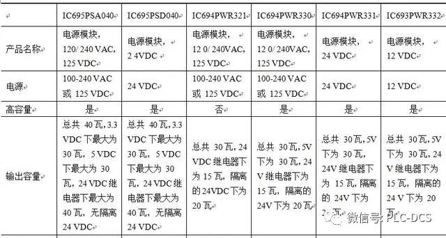
Model and performance parameters of the power module of the RX3i
Shenzhen Hongjiali New Energy Co., Ltd. , https://www.hjlcharger.com