STM32 timers include basic timers, general timers and advanced timers. Among them, TIM6 and TIM7 are the basic timers in STM32. As a beginner, it is easiest to learn from the most basic. Below we use this timer to achieve millisecond Delay function to get started with the application of STM32 timer.
To learn a single-chip microcomputer is to learn to use its registers. Even if you use library functions, registers must be learned.
The registers of TIM6 TIM7 are as follows:
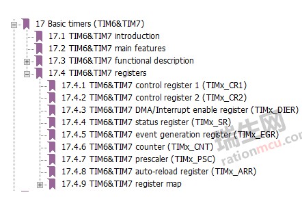
Take a look at the registers first. CR1 and CR1 are control registers, SR is the status register, ARR is the overflow value register, CNT is the current value of the counter, and PSC is the prescaler register. Prescaler register? I'm dumbfounded. I can understand the first few registers. When I hear the prescaler register, I don't seem to know what it is for. Ruishenglai will explain to you. You can write a value from 0 to 65535 in the prescaler register. This value +1 is the clock that the timer runs on. For example, if the microcontroller works at 72MHz, the prescaler register writes 0, the prescaler coefficient is 0+1=1, and the timer clock is 72MHz/1=72MHz; for another example, the microcontroller is still working At the main frequency of 72MHz, write 71 in the prescaler register, the prescaler coefficient is 71+1=72, and the timer clock is 72MHz/72=1MHz. What is the use of knowing the timer clock? I believe many beginners are not clear. The timer clock is related to the time interval at which the timer counter CNT is incremented. According to the frequency and period formula f=1/T, the time interval at which the timer counter increments is 1/timer clock, for example, when When the timer clock is 1MHz, the time interval for the timer counter to increment is 1/1MHz=1 microsecond. At this time, if you set the overflow value to 1000, it means 1000*1us=1ms overflow.
1. Direct manipulation of registers
Below, we first write a millisecond delay function by directly operating the register:
voiddelay_ms(uint16_tms)(TIM6->PSC=35999;TIM6->ARR=ms*2;TIM6->CR1|=(1CR1|=0x1;while((TIM6->SR&0X1)==0);TIM6->SR =0;}
In the first sentence, set the prescaler coefficient to 35999+1=36000, so the timer clock is 72000000/36000=2000Hz, then the timing interval is 1/2000=0.0005 seconds, which is 0.5 milliseconds.
In the second sentence, set the overflow value to ms multiplied by 2. If you want to delay 1 second, the function parameter ms is 1000, and the overflow value is 1000*2=2000, 2000*0.5 milliseconds=1000 milliseconds, that is, 1 second. At this time, some people will say, why not just set the prescaler value PSC to 71999, that is, the prescaler coefficient is 72000, the timer clock is 72000000/72000=1000Hz, and the timing time is 1 millisecond, then directly set the function The parameter ms can be given to the overflow value register ARR, so there is no need to multiply it by 2. The idea is yes, but you have to know that timers are all 16 bits, so the maximum value of PSC is 65535, not 71999. Do you understand now?
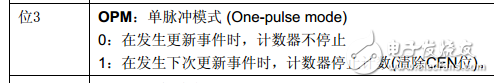
The third statement, CR1 register bit3 is written 1, which is known from the register definition, this is to set the timer to stop the timer once an overflow occurs, because we are doing a delay function, after the delay is over, there is no need Let the timer continue to increment, so set it like this.
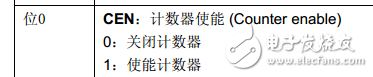
In the fourth statement, write 1 to the CR1 register bit0 to turn on the timer, and the timer counter starts to increment from 0.
The fifth sentence is to check whether bit0UIF in the status register SR is set to 1, when set to 1, the timing value reaches the overflow value, indicating that the timing time is up.
The sixth statement clears the UIF bit caused by the overflow in the status register SR.
2. Use library functions
Next, let's see how to use the library function to implement the millisecond delay function:
voidTIM6_Delay_ms(uint16_tms){/*Define a timer basic timing initialization structure variable*/TIM_TimeBaseInitTypeDefTIM_TimeBaseInitStruct;/*The clock prescaler is 36000, when the main frequency is 72M, the counter will increase by 1 every 500us*/TIM_TimeBaseInitStruct.TIM_Prescaler=35999; /*Auto-reload register value*/TIM_TimeBaseInitStruct.TIM_Period=ms*2;/*Configure the above value to the register*/TIM_TimeBaseInit(TIM6,&TIM_TimeBaseInitStruct);/*Set the timer to stop the timer count after the time is up*/TIM_SelectOnePulseMode( TIM6,TIM_OPMode_Single);/*Clear the UIF flag in SR*/TIM_ClearFlag(TIM6,TIM_IT_Update);/*Open timer 6*/TIM_Cmd(TIM6,ENABLE);/*Detect whether the timing time has come*/while(TIM_GetFlagStatus( TIM6,TIM_IT_Update)==RESET);/*Software clear update flag*/TIM_ClearFlag(TIM6,TIM_IT_Update);}
You can take a closer look at the above library functions. In fact, they are the same as direct manipulation of registers. For example, let's look at the library function TIM_Cmd(TIM6, ENABLE) that opens the timer. We open this function as follows:
voidTIM_Cmd(TIM_TypeDef*TIMx,FunctionalStateNewState){/*Checktheparameters*/assert_param(IS_TIM_ALL_PERIPH(TIMx));assert_param(IS_FUNCTIONAL_STATE(NewState));if(NewState!=DISABLE){/CR*EnabletheTIMCounter*/EN=DISABLE){/CR*EnabletheTIMCounter*/TIMx-> ;}else{/*DisabletheTIMCounter*/TIMx->CR1&=(uint16_t)(~((uint16_t)TIM_CR1_CEN));}}
Bring in the parameters TIM6 and ENABLE, you will find that, in fact, we directly manipulate the register TIM6->CR1|=0X1.
You can open and study other library functions yourself.
In addition, there is a difference between the library function and our direct manipulation of the register, that is, the last statement in the TIM_TimeBaseInit() function. It writes 1 to the bit0 of the TIMx->EGR register, which makes the bit0UIF in the SR set to 1, so in After executing the TIM_TimeBaseInit() function, we will use the TIM_ClearFlag(TIM6, TIM_IT_Update); function to clear the UIF to 0. Otherwise, you will directly detect that the UIF is set to 1, but this setting is not caused by overflow. It is generated by writing 1 to EGR just now, and the delay effect will not be achieved.
In summary, when using the above two delay functions, remember to allow the TIM6 peripheral first, that is, write 1 to bit 4 of the APB1ENR register. Or directly use the library function RCC_APB1PeriphClockCmd(RCC_APB1Periph_TIM6, ENABLE). From the above library functions and the delay function that directly manipulates the registers, you can see that even if you don't need to comment, you can see what you are doing when using the library functions, but you can't tell if you directly manipulate the registers. In actual use, there is no need to entangle the choice between library functions and direct manipulation of registers. I like to use library functions for a while and manipulate registers directly for a while. What do you want? However, the boss of the company definitely wants to use library functions, because if you quit your job and the person who succeeds you sees a bunch of codes for manipulating registers, why should he be embarrassed?
Modular Plugs
Various plugs available with and without shielding options suitable for Cat3, Cat5e and Cat6 applications
Modular plugs offer exceptional performance for voice, data and high-speed networking applications. Plugs are available in four, six and eight-circuit configurations. Our complete offering of hand and production tools helps to make termination easy.
Modular Plug, Ethernet Connectors,Modular Plug 6P6C, 6P4C,,6P2C,CAT6 Modular Plugs,CAT5E Modular Plugs,RJ45 8P8C Modular Plug
ShenZhen Antenk Electronics Co,Ltd , https://www.antenkconn.com