This article shares the design of two liquid level control systems based on single-chip microcomputer.
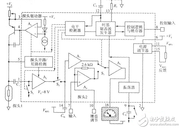
Design of liquid level control system based on single chip microcomputerThe integrated chip LM1042 is a dedicated integrated circuit for detecting liquid level. It integrates all the monitoring circuits required to control the thermal resistance probe, detect the short circuit and open circuit of the thermal resistance probe, and has a strong function. The LM1042 uses a thermal resistance probe technology to measure the non-flammable liquid level, provides a proportional output to the liquid level, and can perform single or repeated measurements. All control thermal resistance probes, short circuit detection of thermal resistance probes. The monitoring circuits required for the open circuit are integrated inside the LM1042 chip. In addition, the chip can use linear input or other sensor signals as input signals.
The LM1042 liquid level detector can be selected as a thermal resistance or linear signal as an input. It has a control circuit integrated with a thermal resistance probe. The LM1042 liquid level detector switches at reset. The delay function prevents the influence of transient signals. In addition, the LM1042 liquid The bit detector has a probe short circuit, and the integrated chip LM1042 is a dedicated integrated circuit for detecting the liquid level. It integrates all the monitoring circuits for controlling the thermal resistance probe, detecting the short circuit of the thermal resistance probe and opening the circuit. Strong function.
LM1042 internal circuit block diagram
The LM1042 uses a thermal resistance probe technology to measure the non-flammable liquid level, provides a proportional output to the liquid level, and can perform single or repeated measurements. All control thermal resistance probes, short circuit detection of thermal resistance probes. The monitoring circuits required for the open circuit are integrated inside the LM1042 chip. In addition, the chip can use linear input or other sensor signals as input signals. The LM1042 liquid level detector can be selected as a thermal resistance or linear signal as an input. It has a control circuit integrated with a thermal resistance probe. The LM1042 liquid level detector switches at reset. The delay function prevents the influence of transient signals. In addition, the LM1042 liquid The bit detector has a probe short circuit and an open circuit detection function.
Overall plan introductionMeasurement section: The liquid level sensor uses the LM1042 liquid level detector and is connected to an analog channel of ADC0809 at the port. The ADC0809 is directly connected to the parallel port expansion chip 8155, and the A, B, and C of the ADC0809 are grounded to select the first analog channel.
Keyboard section: Since the keyboard is not commonly used, the input of the upper and lower limits is interrupted. One is connected to the interrupt port 1, and the other is connected to the timer counter 0 to expand the timer counter 0 to the external interrupt port.
Display part: This part is used to display the liquid level by the liquid crystal display 1602, and the liquid level display shows the value of the liquid level.
Alarm part: When the liquid level is higher than the upper limit of the liquid level input by the keyboard or lower than the lower limit of the liquid level input by the keyboard, the buzzer sounds an alarm.
Control part: When the liquid level is higher than the upper limit of the liquid level input by the keyboard, the single-chip microcomputer starts the motor to open the liquid to discharge the liquid; when the liquid level is lower than the lower limit of the liquid level, the single-chip microcomputer starts the motor to automatically liquid. In order to reduce the influence of the actuator on the single chip microcomputer and improve the stability, an opto-isolator is added in front of the actuator, and the switch of the motor is controlled by the electromagnetic relay.
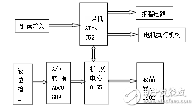
Overall block diagram of the system
The main program flow chart of this program is as follows
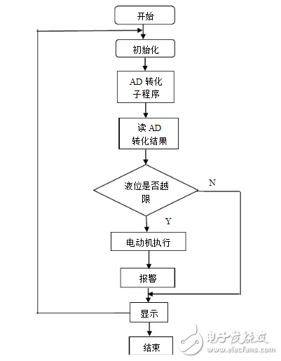
Main program flow chart
The program has a measurement module, an AD conversion module, a keyboard input module, and the like. The interconnection of the various parts should be considered in the programming. Initialize in the main program, the initialization process includes CPU open interrupt, allow external 0, 1 interrupt, set the external interrupt trigger mode to edge trigger, allow T0 interrupt, set the counter to work in mode 2, set the initial value of the counter For all 1, start counter, interrupt priority setting, which sets external interrupt 1, counter T0 is advanced interrupt, let K=0 (use K to detect whether there is a key press, when there is a numeric key press K= 1).
Linear Array Sensor,Infrared Light Detector Device,Swir Linear Detector,Infrared Ingaas Sensor
Ningbo NaXin Perception Intelligent Technology CO., Ltd. , https://www.nicswir.com