Designing research into high-performance, high-precision microprocessors (MPUs) for defense and civilian needs has become important and urgent. In order to process a large amount of real data, and consider the calculation accuracy and real-time performance, it is necessary to separate the MPU separately for a floating point operation. Like the current high-end digital signal processing chip (DSP), which contains an FPU, a high-performance floating-point operation is developed. Unit IP is of great significance [1].
The concept and principle of the microprogram was first proposed by MV Wilks, a professor of mathematics at the University of Cambridge in 1951, [2], but in the following 15 years, the development of microprogramming technology was constrained by the problem of controlling memory. Due to the development of LSI and VLSI control memories, microprograms have begun to play an important role in microcomputers.
Microprogram control's performance is a key factor to improve the processing speed. The research on micro-program controller in this thesis is based on the design of 32-bit FPU of Harbin Institute of Technology (Weihai) Microelectronics Center. It adopts the method of micro-instruction control, completes the design of related modules with gate level, and the results after layout and wiring. It can be seen that the design is small in scale and high in speed, which is very suitable for embedded applications.
2 Micro-program controller structure and designThe generation of control signals in the microprocessor is typically accomplished by both a microprogram and a state machine, where the microprograms are firmware. The microinstruction output from the microprogram controller is used to control the operation of the entire FPU [3]. A microprogram generally consists of two parts: operational control and sequential control. The control section is used to manage and direct the work of the FPU [4]. The sequence control portion of the microprogram is used to determine the address at which the next microinstruction is generated. Microprogram controllers have their own advantages, such as: a set of advantages such as regularity, flexibility and maintainability. The structure of the microprogram controller of this design is shown in Figure 1.
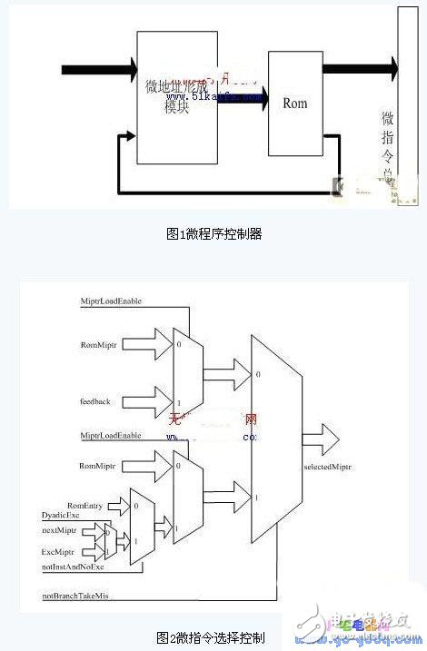
The microprogram controller mainly includes three parts, a micro address generation module for generating the next micro instruction, a memory for storing the micro instruction (this is a Rom), and a control bus for directing the operation of the FPU, wherein the first two are the first two. Part, the following are introduced separately:
2.1 Introduction to Micro Address Generation Module
The main purpose of the micro address generation module is to generate the address of the next microinstruction. The address line width is 8 bits, and the next micro address is generated by the following (as shown in Figure 2):
1. The ExcMiptr signal is used to select the entry address of the exception operation and control corresponding to various exceptions (including inaccurate exceptions, overflows, underflows, and invalid exceptions) during the execution of an FPU instruction.
2. The nextMiptr signal is used to select an FPU instruction execution process to generate the address of the next micro-instruction under normal conditions.
3. The RomEntry signal is used to select the entry address of different instructions according to the FPU instruction. This design has different control entry addresses for the instructions of addition, subtraction, multiplication, division, multiplication and addition of single precision and double precision.
4.RomMiptr signal is the default docking address of the micro address, that is, the default address output when the reset and FPU are idle.
5. The feedback signal is used to select the jump instruction used to jump to the microinstruction address, such as the multiply, multiply, and subtract instructions in this design.
The control of these address signals as above is derived from the control bits of the microinstruction. The control for whether or not to generate a branch is shown in Fig. 3.
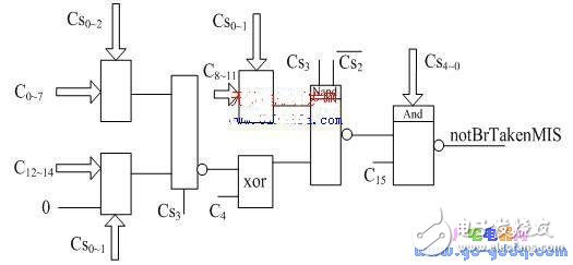
Figure 3 Micro-instruction branch control signal generation diagram
Pressure Gauges,Door Pressure Gauge,Differential Pressure Gauge,Stainless Steel Manometer
ZHOUSHAN JIAERLING METER CO.,LTD , https://www.zsjrlmeter.com