The characteristics related to the reliability of the resistor are: temperature coefficient, rated power, rated voltage, inherent noise, and life expectancy.
First, the temperature coefficient
The temperature coefficient of resistance (TCR) indicates the relative change in resistance when the temperature changes by 1 degree, in ppm/°C (ie, 10E(-6)/°C).
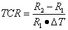
In practical applications, the average temperature coefficient of resistance is usually used, and the formula is: TCR (average) = (R2-R1) / R1 (T2-T1)
There is a negative temperature coefficient, a positive temperature coefficient, and a critical temperature coefficient at which the resistance will only mutate at a certain temperature.
The temperature coefficient of resistance of copper is 1/234.5 °C.
The temperature stability of different types of resistors is from excellent to secondary, in order: metal foil, wire wound, metal film, metal oxide film, carbon film, organic solid core.
1. Gold plating is not intended to reduce electrical resistance, but because the chemical properties of gold are very stable and are not easily oxidized. Gold plating on the joint is to prevent poor contact (not because gold has better conductivity than copper).
2. It is well known that silver has the lowest resistivity and its conductivity is best among all metals.
3. Don't think that gold-plated or silver-plated boards are good. Good circuit design and PCB design have a greater impact on circuit performance than gold plating or silver plating.
4. Conductive power is better than copper, copper is better than gold! Now attach the resistivity of common metals and their temperature coefficient:
Material temperature t/°C resistivity resistance temperature coefficient aR/°C-1
| substance | Temperature t/°C | Resistivity Ω.m | Temperature coefficient of resistance Ω/°C-1 |
| silver | 20 | 1.586 | 0.0038 (20 ° C) |
| copper | 20 | 1.678 | 0.00393 (20 ° C) |
| gold | 20 | 2.40 | 0.00324 (20 ° C) |
| aluminum | 20 | 2.6548 | 0.00429 (20 ° C) |
| calcium | 0 | 3.91 | 0.00416 (0 ° C) |
| beryllium | 20 | 4.0 | 0.025 (20 ° C) |
| magnesium | 20 | 4.45 | 0.0165 (20 ° C) |
| molybdenum | 0 | 5.2 | |
| iridium | 20 | 5.3 | 0.003925 (0 ° C ~ 100 ° C) |
| Tungsten | 27 | 5.65 | |
| Zinc | 20 | 5.196 | 0.00419 (0 ° C ~ 100 ° C) |
| cobalt | 20 | 6.64 | 0.00604 (0 ° C ~ 100 ° C) |
| nickel | 20 | 6.84 | 0.0069 (0 ° C ~ 100 ° C) |
| cadmium | 0 | 6.83 | 0.0042 (0 ° C ~ 100 ° C) |
| indium | 20 | 8.37 | |
| iron | 20 | 9.71 | 0.00651 (20 ° C) |
| platinum | 20 | 10.6 | 0.00374 (0 ° C ~ 60 ° C) |
| tin | 0 | 11.0 | 0.0047 (0 ° C ~ 100 ° C) |
| rubidium | 20 | 12.5 | |
| chromium | 0 | 12.9 | 0.003 (0 ° C ~ 100 ° C) |
| gallium | 20 | 17.4 | |
| thallium | 0 | 18.0 | |
| cesium | 20 | 20 | |
| lead | 20 | 20.684 | (0.0037620 ° C ~ 40 ° C) |
| antimony | 0 | 39.0 | |
| titanium | 20 | 42.0 | |
| HG | 50 | 98.4 | |
| manganese | 23~100 | 185.0 |
Second, the rated power of the resistor
Chip resistors are currently the most common package of 10, and are also represented by two size codes. One size code is coded by the EIA (American Electronics Industry Association) code, and the other first two digits and the last two digits represent the length and width of the resistor, in inches. For example, the 0603 package we often say refers to the English code. The other type 1608 is a metric code, also represented by a 4-digit number, in millimeters.
SMD resistor package representation and corresponding power customers are often mistaken, we want to make customers more fast and convenient query. To this end, we have developed a relationship between the inch and metric relationship of the chip resistor package and the detailed dimensions and corresponding power for the query.
| Imperial | Metric | power | Length: L (mm) | Width: W (mm) | Height: T (mm) | Positive electrode (mm) | Back electrode (mm) |
| 01005 | 0402 | 1/32W | 0.40±0.03 | 0.20±0.03 | 0.13±0.05 | 0.10±0.05 | 0.10±0.05 |
| 0201 | 0603 | 1/20W | 0.60±0.03 | 0.30±0.03 | 0.23±0.03 | 0.10±0.05 | 0.15±0.05 |
| 0402 | 1005 | 1/16W | 1.00±0.10 | 0.50±0.05 | 0.35±0.05 | 0.20±0.10 | 0.25±0.10 |
| 0603 | 1608 | 1/10W | 1.60±0.10 | 0.80±0.15 | 0.45±0.10 | 0.30±0.20 | 0.30±0.20 |
| 0805 | 2012 | 1/8W | 2.00±0.15 | 1.25±0.15 | 0.55±0.10 | 0.45±0.20 | 0.40±0.20 |
| 1206 | 3216 | 1/4W | 3.10±0.15 | 1.55±0.15 | 0.55±0.10 | 0.45±0.20 | 0.45±0.20 |
| 1210 | 3225 | 1/2W | 3.10±0.10 | 2.60±0.15 | 0.55±0.10 | 0.50±0.25 | 0.50±0.20 |
| 1812 | 4832 | 1/2W | 4.50±0.20 | 3.20±0.20 | 0.55±0.20 | 0.50±0.20 | 0.50±0.20 |
| 2010 | 5025 | 3/4W | 5.00±0.10 | 2.50±0.15 | 0.55±0.10 | 0.60±0.25 | 0.50±0.20 |
| 2512 | 6432 | 1W | 6.35±0.10 | 3.20±0.15 | 0.55±0.10 | 0.60±0.25 | 0.50±0.20 |
Resistor derating specification
Steady state power and transient power
Steady state power
The power derating is the derating at the corresponding operating temperature, that is, the further derating of the power at the ambient temperature specified by the component, and is calculated using the P=V2/R formula.
In order to ensure the normal operation of the resistor, various types of resistor manufacturers have determined the corresponding power reduction curve through experiments. Therefore, in the course of use, the resistor must be used strictly according to the power reduction curve.
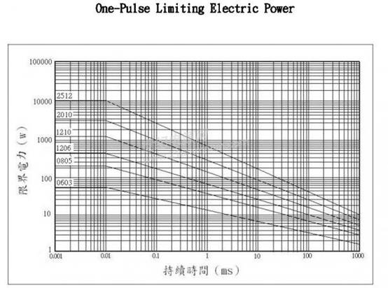
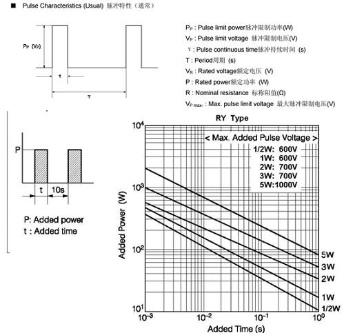
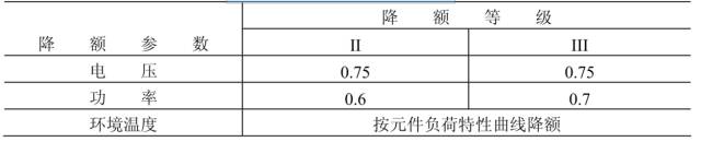
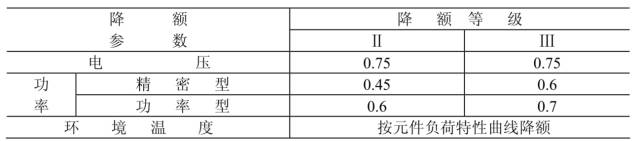
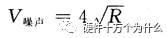
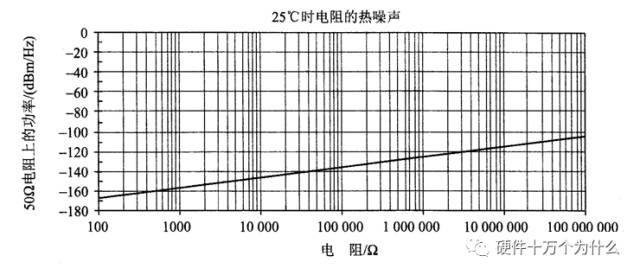
When the ambient temperature is set at the rated temperature (T P=PR(0.6+(Ts-T)/(Tmax-Ts)) PR is rated power consumption; T is the ambient temperature; Tmax is the maximum ambient temperature at zero power consumption. Transient power Different manufacturers, the conversion curve of resistance pulse power consumption and steady state power are different. In specific applications, the conversion defect is to be queried, the transient power is converted to steady state power, and then derating is performed on this basis. The factory rated ambient temperature is 70 ° C, below this temperature, directly derated according to 60%. When this temperature is exceeded, the nominal curve is a diagonal line. The derating curve is also in accordance with the maximum temperature derating of 121 ° C, then draw a red diagonal line, derated according to the diagonal line. Transient derating is long enough that the resistor can withstand much higher transient power than the rated power. Refer to the highest overload voltage parameter in the manufacturer's data and derate it on this basis. Transient power consumption is discussed and analyzed separately according to single pulse and multiple pulses. Single pulse: Multiple pulses: 1, synthetic resistor 1.1 Overview Synthetic resistors have small size and strong overload capability, but their resistance stability is poor, heat and current noise are large, and voltage and temperature coefficients are large. The main derating parameters for a composite resistor are ambient temperature, power, and voltage. 1.2 Application Guide a) Synthetic resistors are negative temperature and negative voltage coefficient and are prone to burnout. Therefore limiting its voltage is a must. b) Synthetic resistors used in wet conditions should not be excessively derated. Otherwise, the moisture will not volatilize and it may make The resistor has failed. c) Excessive hot spot temperature may cause permanent damage to the resistive material inside the composite resistor. d) In order to ensure the reliability of the long-term operation of the circuit, the circuit design shall allow the composite resistor to have a resistance tolerance of ±15%. 1.3 Derating guidelines The derating criteria for the composite resistor are shown in the table below. Synthetic resistor derating criteria 2, film type resistor 2.1 Overview According to the structure of the thin film type resistor, there are mainly two kinds of metal oxide film resistors and metal film resistors. Thin film resistors have the highest frequency characteristics, low current noise and nonlinearity, wide resistance range, small temperature coefficient and stable performance. They are the most widely used resistors. The main parameters of the film type resistor derating are voltage, power and ambient temperature. 2.2 Application Guide a) The resistance of various metal oxide film resistors will decrease under high frequency operation (see component related detailed specifications). b) In order to ensure the reliability of the long-term operation of the circuit, the design shall allow the film type resistor to have a certain resistance tolerance, the metal film resistor is ±2%, the metal oxide film resistor is ±4%, and the carbon film resistor is ±15%. 2.3 Derating guidelines 3, resistor network 3.1 Overview The resistor network has high assembly density, good matching performance and tracking temperature coefficient between components, and good stability to time and temperature. The main parameters of the resistor network derating are power, voltage and ambient temperature. 3.2 Application Guide In order to ensure the reliability of the long-term operation of the circuit, the resistor network should be allowed to have a resistance tolerance of ±2%. 3.3 Derating guidelines 4, wire wound resistor 4.1 Overview Wirewound resistors are available in precision and power versions. Wirewound resistors have the advantages of high reliability, good stability, no nonlinearity, and low current noise, temperature and voltage coefficient. The main parameters of the wirewound resistor derating are power, voltage and ambient temperature. 4.2 Application Guide a) Resistors with a wire diameter less than 0.025 mm are not used under Class II derating applications. b) Power-type wirewound resistors can withstand much higher pulse voltages than steady-state operating voltages, but should be derated in use. See Appendix D (Reference). c) The power rating of the power-type wirewound resistor is related to the heat dissipation area at the bottom of the resistor. This factor should be considered in the derating design. See Appendix E (Reference). d) In order to ensure the reliability of the long-term operation of the circuit, the design shall allow the wirewound resistor to have a certain resistance tolerance: ±0.4% for precision wirewound resistors and ±1.5% for power wirewound resistors. 4.3 Derating guidelines 5, thermistor 5.1 Overview The varistor has a very high resistance - temperature coefficient (positive or negative). The main parameters of the varistor derating are rated power and ambient temperature. 5.6.5.2 Application Guide a) For the negative temperature coefficient type thermistor, a current limiting resistor should be used to prevent the component from being out of control. b) Under no circumstances should the maximum current and power of the resistor be exceeded, even for short periods of time. c) To ensure long-term reliability of the circuit, the design shall allow a ±5% tolerance of the thermistor resistance. 4.3 Derating guidelines Third, several other parameters: Rated voltage: The voltage converted from resistance and rated power. Maximum operating voltage: The maximum continuous operating voltage allowed. The maximum operating voltage is low when operating at low air pressure. Aging coefficient: The percentage of the relative change in resistance of a resistor under rated power for a long period of time. It is a parameter indicating the length of life of the resistor. Voltage coefficient: The relative change in resistance of the resistor for every 1 volt change in the specified voltage range. Noise: An irregular voltage fluctuation generated in a resistor, including thermal noise and current noise. The thermal noise is due to the irregular movement of electrons inside the conductor, causing the voltage of any two points of the conductor to change irregularly. At any temperature above absolute 0 (-273 ° C or Ok), the electrons in the material are continuously moving thermally. Since the direction of motion is random, any short-term current is irrelevant, so there is no detectable current. However, continuous random motion sequences can result in Johnson noise or thermal noise. The magnitude of the resistance thermal noise has the following relationship with its resistance; Where Vn is the noise voltage in V; Kb is the Boltzmann constant, 1.38 × 10 (-23) J / K; T is the temperature, in K; R is the resistance, in Ω; B is the bandwidth in Hz. At room temperature, it can be simplified to the following expression: The figure shows the thermal noise power generated by a 50 Ω termination resistor at 25 °C. The relationship between thermal noise and resistance and thermal noise at 25 °C Although the noise voltage and power are very low, if the resistor is in a high gain active filter, the noise may be significant. The noise is proportional to the square root of the temperature and resistance. The wider the bandwidth, the greater the total power, so even if the power amplitude of dBm/Hz looks small, the total power in a given bandwidth will be high. If you use V noise Fourth, the factors affecting the life of the resistor 1. Temperature, too high temperature can quickly burn it 2. The pH of the environment, direct corrosion resistance causes its damage 3. External force, beyond the limit of a certain force, the resistance will break, so if The life of the resistor is prolonged, the heat dissipation is good, the burning is prevented, the environment is dry, no pollutants, and external force is avoided. A resistor with a large resistance value has a relatively long life The resistance of 1M ohm is very high. When used in low voltage, the power consumption is small, the working environment is little affected, and the life is very long. No special attention is required (relative to other components such as electrolytic capacitors). Most of the problems are caused by working at high pressure. When working at high voltage, the manufacturing process and materials used in the resistors have considerable requirements. It is often used to consider the power used. The safe power value of the resistor is more than twice the actual working power. Some products are not properly designed and often used. The power and resistance ratings are too close); so temperature tolerance is the most basic requirement. The instantaneous pulse voltage and surge current will also cause a fatal blow to the resistor. For products with poor pin soldering and defective soldering process, it will not crash for a long time. The correct use of the resistor, the service life of more than 100,000 hours is not a problem. . Therefore, high-resistance resistors such as 1M ohms are distinguished from high voltage and general purpose. The price of high-voltage dedicated resistors is several times higher than the general resistance, but the resistors are ultimately low-cost components, and the number of resistors used at high voltage is not much. For the high-voltage and high-current scene, there is enough derating design to effectively improve the life of the resistor. PU Leather Flip Cover Shockproof Case PU Leather Flip Cover Shockproof Case,Pu Leather Case,Genuine Pu Leather Case,Best Premium Pu Leather Case Guangzhou Jiaqi International Trade Co., Ltd , https://www.make-case.com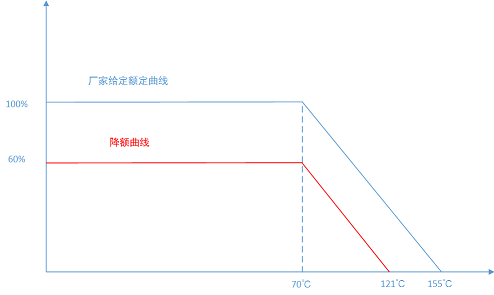


 The terminal is converted to power, where the R terminal is the noise termination resistor and then multiplied by the total bandwidth in Hz, then the resulting total noise power over the entire bandwidth may be unacceptable for low noise applications.