The bus has the advantages of simple structure and low cost. However, when engineers set up the RS-485 bus network, in order to improve the reliability of the entire network communication, it is necessary to encounter a problem often: need to add a terminal resistor? This article will answer you.
1, the role of the terminal resistance
For the RS-485 bus, the terminating resistor is mainly used to match the characteristic impedance of the communication line, prevent signal reflection, and improve signal quality.
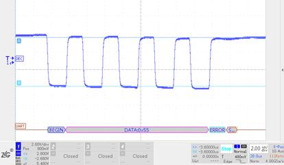
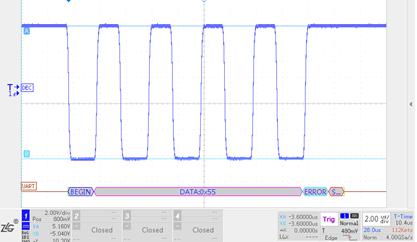
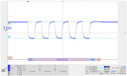
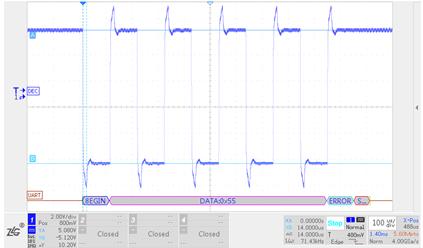
When constructing an RS-485 bus network, shielded twisted pair with a characteristic impedance of 120Ω is usually used. Since the input impedance of the RS-485 transceiver is generally high (for example, the input impedance of the RSM485ECHT is 96kΩ, up to 256 nodes can be connected). When transmitted to the end of the bus, the instantaneous impedance is abrupt (in the case of RSM485ECHT, the impedance is changed from 120Ω to 96kΩ), causing the signal to reflect and affect the quality of the signal. RSM485ECHT in the case of 1200m, 500kbps communication rate without the termination resistor and the addition of the terminal resistance waveform as shown in Figure 1 and Figure 2, the termination resistance significantly improved the signal quality.

1 RSM485ECHT 1200m 500kbps without termination resistor
2 RSM485ECHT 1200m 500kbps plus terminating resistor
2, the problem caused by the terminal resistance
Although the terminating resistor can improve the signal quality, it also has the following problems:
1) Reduce the amplitude of the drive signal
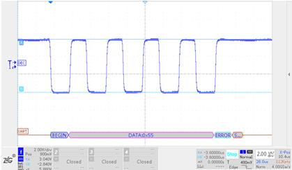
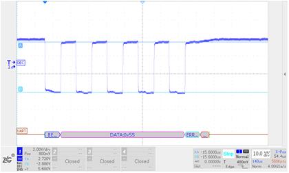
The larger the load on the RS-485 bus, the lower the amplitude of the differential voltage of the RS-485 transceiver output. The waveform of the RSM485ECHT without the terminating resistor and the terminating resistor at 5m, 500kbps is shown in Figure 3 and Figure 4. It can be seen that the drive signal is reduced by about 2V after increasing the termination resistance.
3 RSM485ECHT 5m 500kbps without terminal
4 RSM485ECHT 5m 500kbps plus terminal
2) Increase the voltage drop on the communication line
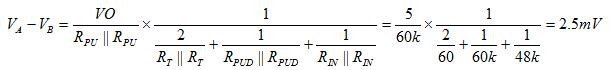
Increasing the terminating resistor increases the current on the communication cable, creating a large differential voltage and reducing the amplitude of the signal at the receiving end. The signal waveform of the RSM485ECHT at the head end and end of the 1200m, 115.2kbps is shown in Figure 5 and Figure 6 (0.75mm2 communication line), and the end signal is reduced by about 0.7V compared with the head end signal.
5 RSM485ECHT 1200m 115.2kbps plus termination resistor head end waveform
6 RSM485ECHT 1200m 115.2kbps plus terminal resistance end waveform
3) Increase the power consumption of the transceiver
Increasing the terminating resistance has little effect on the operating current in the receiving state, but greatly increases the operating current in the driving state. Taking RSM485ECHT as an example, when RSM485ECHT is in the receiving state, the working current is about 20mA. When the driving state is not connected with the terminating resistor, the working current is about 27mA. When the driving state is added with the terminating resistor, the working current is about 83mA. It can be seen that the terminating resistance is greatly increased. The power consumption of the RS-485 transceiver should be used with caution for applications with power requirements.
4) Reduce the differential voltage when the bus is idle
Figure 7 shows a schematic diagram of two RSM485 ECHT communications.

7 RSM485ECHT communication equivalent diagram
When both modules are in the receiving state, the following formulas can be listed for Node A and Node B according to Kirchhoff's current law:
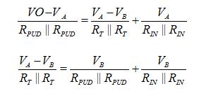
Among them: RPUD is RSM485ECHT built-in pull-up resistor, 120kΩ; R-IN is RSM485ECHT input impedance, 96kΩ; according to the above formula, the differential voltage between AB can be calculated as:
Since the threshold level of the RSM485ECHT is -200mV to -40mV, in the above case, the module still outputs a high level to ensure that the data is not received by mistake when the bus is idle. However, for an RS-485 transceiver with a threshold level of -200mV to +200mV, the output level is in an indeterminate state, and data may be received by mistake at this time.
3. How to solve the problem of adding idle state after the terminal resistance?
There are two workarounds for the problem of idle state:
1) Use a module similar to RSM485ECHT (threshold level is -200mV ~ -40mV). When the differential voltage of RS-485 bus is greater than -40mV, the output of RS-485 transceiver is high level.
2) Using a module with an output isolated power supply such as RSM485PCHT or RSM485PHT, the voltage in the idle state of the RS-485 bus can be pulled to +200mV or more by adding a small pull-up resistor externally (generally 100mV or 200mV is required) The above margin) ensures that the RS-485 bus differential voltage is not within the threshold level when idle, but the pull-down resistor value cannot be too small. Generally, the bus pull-up (or pull-down) parallel value is greater than 375Ω.
4. When do I need to add a terminating resistor?
1) It is recommended not to add a terminating resistor when the communication speed is low or the communication distance is short.
When the communication speed is low or the communication distance is short, the signal reflection has little effect on the communication signal, and the power consumption can be greatly reduced without adding the terminating resistor, and the RS-485 bus can be guaranteed to be idle by adding a large pull-down resistor value. With a higher differential voltage amplitude, the reliability of communication is improved.
2) The communication distance is long and the communication speed is fast, and the signal quality is high.
At this point, the termination resistance can be increased to prevent signal reflection problems caused by sudden changes in impedance and improve signal quality, but it should be ensured that the differential voltage of the bus is not within the threshold level when the bus is idle.
3) The case where the power consumption is required and the communication distance is long
The reflected signal bounces back and forth on the bus and the reflected signal is gradually consumed. For serial communication, the MCU generally samples the signal at the middle of one bit. Because of the low communication speed, the time of each bit is longer, so the reflected signal is consumed when the sampling point is reached, and there is no communication. influences. The waveform of the RSM485ECHT at the first end and the end of the 1200m 9600bps without the termination resistor is shown in Figure 8 and Figure 9. It can be seen that the reflected signal is already consumed before reaching the middle of each bit.
Therefore, for applications where the power consumption of the RS-485 transceiver is high and the communication distance is long, the communication speed should be appropriately reduced.
8 RSM485ECHT 1200m 9600bps without terminal headend waveform
9 RSM485ECHT 1200m 9600bps without terminal end waveform
According to the outer diameter of the speakers, we have speakers from 0.4"(10mm) to 5"(128mm).
We divided them into:
1) 0.4"~0.95" speaker (10~24mm)
2) 1"~1.4" speaker (26~36mm)
3) 1.5"~2" speaker (40~50mm)
4) 2.05"~2.75" speaker (52~70mm)
5) 3"~5" speaker (76~128mm)


FAQ
Q1. What is the MOQ?
XDEC: 2000pcs for one model.
Q2. What is the delivery lead time?
XDEC: 15 days for normal orders, 10 days for urgent orders.
Q3. What are the payment methods?
XDEC: T/T, PayPal, Western Union, Money Gram.
Q4. Can you offer samples for testing?
XDEC: Yes, we offer free samples.
Q5. How soon can you send samples?
XDEC: We can send samples in 3-5 days.
Small Speakers,Large Speakers,Huge Speakers,Mini Speakers
Shenzhen Xuanda Electronics Co., Ltd. , https://www.xdecspeaker.com