Compared with electromagnetic voltage transformers, Hall voltage sensors have the advantages of small size, light weight, wide frequency band, AC and DC, etc., and have been widely used in the field of industrial measurement and control.
With the rapid development of power electronics technology, the frequency conversion speed regulation technology is more and more widely used in motor drive. The accurate energy efficiency measurement and detection of the motor system using the frequency conversion speed regulation technology is not only the detection of the energy saving effect of the frequency conversion speed regulation technology. It is also the basis for scientific and sustainable development of frequency control technology. The Hall voltage sensor is the main measuring device for the test and energy efficiency measurement and testing of frequency converters such as inverters and wind turbines, AC traction motors and electric vehicle motors. This paper aims to understand the main characteristics of the Hall voltage sensor by analyzing the principle of the Hall voltage sensor and to guide the engineering application.

Figure 1 Hall voltage sensor physical map
Two Hall voltage sensor principle
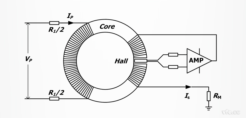
As shown in FIG. 2, the Hall voltage sensor mainly includes a primary coil, a magnetic ring, a secondary coil, an amplifying circuit, and a current limiting resistor R connected in series with the primary coil. The current limiting resistor R is thrown away and the remainder is equivalent to a closed-loop Hall current sensor. The difference is that the primary current of the sensor is very small, typically milliampere.
Intuitive analysis: Small signal measurement is difficult and measurement accuracy is low. Therefore, the Hall effect sensor based on Hall effect is far lower than Hall current sensor .

Figure 2 Hall voltage sensor principle
Obviously, the greater the current of the primary coil, the greater the power of the resistor R. Excessive current will bring the following drawbacks:
â—†The sensor consumes a lot of power and affects the circuit under test;
â—†The resistance heat is large, the temperature is high, and the temperature drift has a great influence on the measurement accuracy;
â—† In order to dissipate this heat, the volume of the Hall voltage sensor is inevitably increased, and it is unfavorable for insulation.
The above reasons determine that the input current limiting resistance of the actual Hall voltage sensor is large, and the higher the test voltage, the larger the resistance value.
Three Hall Voltage Sensor Features
The last section analyzes the principle of the Hall voltage sensor. We know that the input of the Hall voltage sensor has a resistor with a large resistance value, and the number of turns of the primary winding is large.
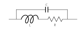
In the objective world, there is no ideal resistance element, because the resistance element itself has a certain shape and volume, which inevitably causes its additional inductance and capacitance. In addition, the distributed inductance and distributed capacitance of the environment also have a certain influence on the resistance element. As shown in FIG. 3, the resistive element can be equivalent to the resistor R in series with the inductor L and then in parallel with the capacitor C.

Figure 3 equivalent circuit of the resistance element connected in series with the Hall voltage sensor
The impedance of the resistive element in Figure 3 is:

In the above formula, Re and Xe are the components of the equivalent resistance and the equivalent reactance components, respectively.
Since L and C are generally small, 1/LC is large, and when ω2<<1/LC and ω<<1/RC, the above equation can be simplified as:

In general, since L is small, the first term can be ignored. For the second term, when R is small, it is very close to R. However, when R is large, RC cannot be ignored.
When RC is not negligible relative to ω, the second term has a large impact on the accuracy and bandwidth of the Hall voltage sensor.
This leads to the first conclusion: the larger the input resistance, the greater the influence of the distribution parameters on the bandwidth of the Hall voltage sensor when using the same technique.
By analyzing the principle of the Hall voltage sensor, we know that the Hall voltage sensor has a large number of turns in the primary coil. The more coil turns, the greater the inductance. Under normal circumstances, multi-turn coils exhibit obvious sensibility and are not suitable for AC voltage testing. However, from the principle analysis of the Hall voltage sensor, it can be seen that when the Hall voltage sensor operates normally, the magnetic induction intensity at the Hall element is zero under the action of the compensation winding magnetic field. If the magnetic induction at the inside and outside of the primary coil is zero, then the actual equivalent inductance of the coil is zero. This is one of the important reasons why Hall voltage sensors are suitable for AC voltage testing and generally have a wide frequency band.
However, it is impossible for the primary coil and the compensation coil to completely overlap. It is impossible for the magnetic field to be zero inside and around the primary coil. The presence of a magnetic field inevitably affects the change of the current and has a certain influence on the bandwidth of the Hall voltage sensor.
In order for the Hall element to have sufficient sensitivity, the smaller the primary current of the Hall voltage sensor, the more turns are required. The more turns, the narrower the bandwidth of the Hall voltage sensor.
This leads to the second conclusion: the more the primary winding turns, the greater the bandwidth to the Hall voltage sensor when using the same technique.
For the Hall voltage sensor, considering that the current will generate heat through the resistor, in general, the higher the measured voltage, the larger the current limiting resistor R, and the greater the influence of the RC on the Hall voltage sensor. The higher the voltage to be measured, the smaller the current of the primary coil and the larger the number of turns of the primary coil.
This is the reason why the same manufacturer's Hall voltage sensor, with the increase of the test voltage, the bandwidth is gradually reduced.
Technical indicators of four commonly used Hall voltage sensors
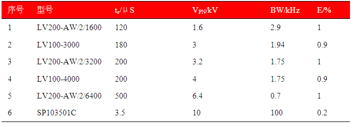
The following table shows the rise time, accuracy and bandwidth of the commonly used Hall voltage sensor and AnyWay's SP103501C variable frequency power sensor. It can be seen from the table that as the test voltage increases, the accuracy of the Hall voltage sensor decreases and the rise time becomes larger. The bandwidth is narrowed.

Table 1 Main technical indicators of common Hall voltage sensors
Note: Since most of the Hall voltage sensors do not disclose bandwidth indicators, the bandwidth can be estimated according to the empirical formula BW=0.35/tr. The bandwidth in the table is calculated according to this formula.
The accuracy and bandwidth of the Hall voltage sensor described in the table are consistent with the analysis of Section 3 as measured. In addition, the 6400V Hall voltage sensor described in the table has a bandwidth of only 700 Hz, which requires special attention when used for AC power.
In the measurement of variable frequency power (also commonly referred to as broadband power measurement), most current variable frequency power analyzers can directly measure voltages within 1kV. Hall voltage sensors are mainly used to measure AC voltages above 1kV, and Hall voltages above 1kV. The sensor has low precision and narrow bandwidth. Users should pay special attention when constructing high-voltage variable frequency power test system above 1kV.
Standard Recovery Stud Diode are mainly used for rectifying and switching
It has positive pressure reduction (0.4v -- 1.0v), short reverse recovery time (2-10ns nanosecond), large reverse leakage current, low pressure resistance, generally lower than 150V, and is used in low voltage situations.
Diodes are electronic devices that have two electrodes that allow only a single current to flow in a single direction.Varicap bond (bond) is an electronic adjustable capacitor.Most diodes have a current orientation that we call reading "rectifier".The most common function of a diode is to allow only the current to pass in one direction (called forward bias) and to block in the opposite direction (called reverse bias).
Standard Recovery Stud Diode,Standard Recovery Diode,400V Standard Recovery Diode,Stud Diode
YANGZHOU POSITIONING TECH CO., LTD. , https://www.cndingweitech.com