S7-200 series give full play to its powerful functions in the distributed automation system. The scope of application can cover the simple control of replacing relays to more complex automatic control. The application fields are extremely wide, covering all industrial and civil fields related to automatic detection and automatic control, including various machine tools, machinery, electrical facilities, civil facilities, environmental protection equipment, etc. Such as: stamping machine tools, grinders, printing machinery, rubber chemical machinery, central air conditioning, elevator control, motion systems.
S7-200 series PLC can provide 4 different basic models of 8 CPUs for your use.
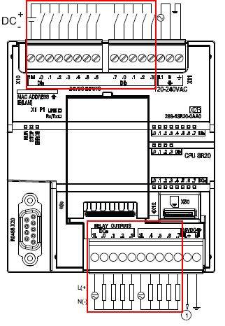
Figure 1. Wiring diagram of CPU SR20
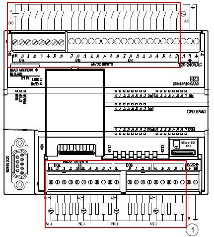
Figure 2. Wiring diagram of CPU SR40

Figure 3. Wiring diagram of CPU CR40
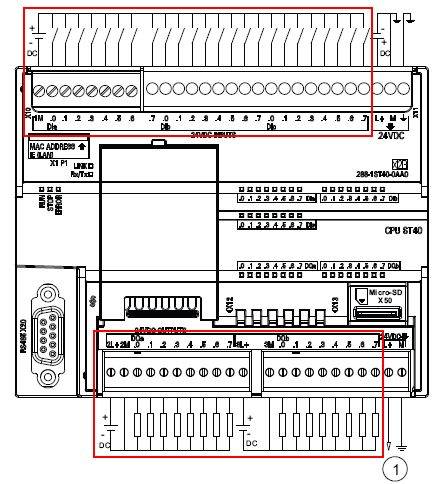
Figure 4. Wiring diagram of CPU ST40
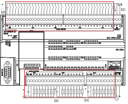
Figure 5. CPU SR60 wiring diagram
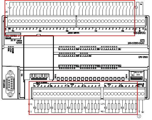
Figure 6. Wiring diagram of CPU ST60
Digital input wiring
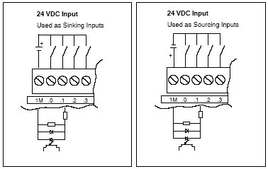
| Figure 7. Sink input connection | Figure 8. Source input connection |
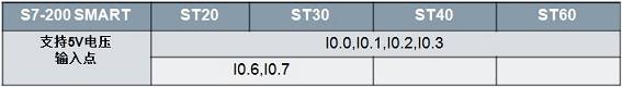
For most inputs, it is 24VDC input. Among them, ST CPU's I0.0-I0.3 supports 5-24V input, and ST20/30's I0.6 and I0.7 also support 5-24V input. As shown in the following table:
The digital input point of S7-200 SMART is a two-way diode inside, which can be connected to sink type (Figure 7) or source type (Figure 8), as long as each group is connected in the same way.
For digital input circuits, the key is to form a current loop. The input points can be connected to different power sources in groups, and there is no connection between these power sources.
Digital output wiring
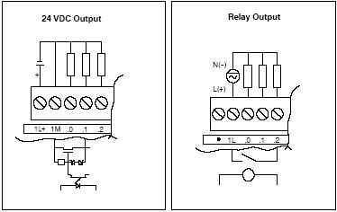
| Figure 9. Source output | Figure 10. Relay output |
The transistor output can only be connected as a source output (Figure 9), and cannot be connected as a sink type, that is, the output is 24V.
The relay output is a group of dry nodes sharing a common terminal, which can be connected to AC or DC, and the voltage level is up to 220V. Example: 24V/110V/220V AC and DC signals can be connected. But it is necessary to ensure that a group of outputs are connected to the same voltage (a group shares a common terminal, such as 1L, 2L). For weak and small signals, such as signals less than 5V, you need to verify the reliability of its output. When the relay output point (Figure 10) is connected to a DC power supply, the common terminal can be connected to either positive or negative.
For digital output circuits, the key is to form a current loop. The output points can be connected to different power supplies in groups, and there is no connection between these power supplies.
Represents 24VDC sensor power output
The pin refers to the connection between the internal circuit of the integrated circuit (chip) and the peripheral circuit, and the pin constitutes the interface of the chip. According to the function, the pins of AT89S52 can be divided into four categories: main power supply, external crystal oscillator or oscillator, multi-function I/O port, and control, strobe and reset.
Terminal Pins,Terminal Hardware Pin,High Precision Terminal Pins,Terminal Pins For Pcb
Sichuan Xinlian electronic science and technology Company , https://www.sztmlch.com