RS-485 interface communication In some cases, such as when a driver releases the bus to another driver, there will be no driving current on the bus for a short time. At this time, the matching resistors at both ends will put the differential bus voltage to 0V, which is an undefined input level for many RS-485 receivers. For this undefined input level, the receiver may output the wrong logic state, or oscillate in worse cases. Oscillation will be misunderstood by the controller as a repeating communication start bit, causing the controller to waste valuable bandwidth to respond to these unreal communication requests. The fail-safe bus bias circuit is one of the methods to solve this problem.
Note: appearing below
VA=

VB=

VAB=

VIT-MAX=

VOD=

RB=

RT1=

RT2=

REQ=

Z0=

RCM=

nUL=

RB/2=

The passive component communication fault-free bias circuit is when there is no drive current on the drive bus (see Figure 1), a resistor network composed of pull-up, termination and pull-down resistors is used to divide the voltage to provide a differential DC bus voltage VAB, and then Ensure that the communication is safe and trouble-free.
If the output of all interface devices is to be driven to a defined high-level idle state, VAB must be higher than the maximum input threshold VIT-MAX. In addition, considering the operating conditions in harsh industrial environments, sufficient noise margin should be added to make VAB = VIT -MAX + VNoise.

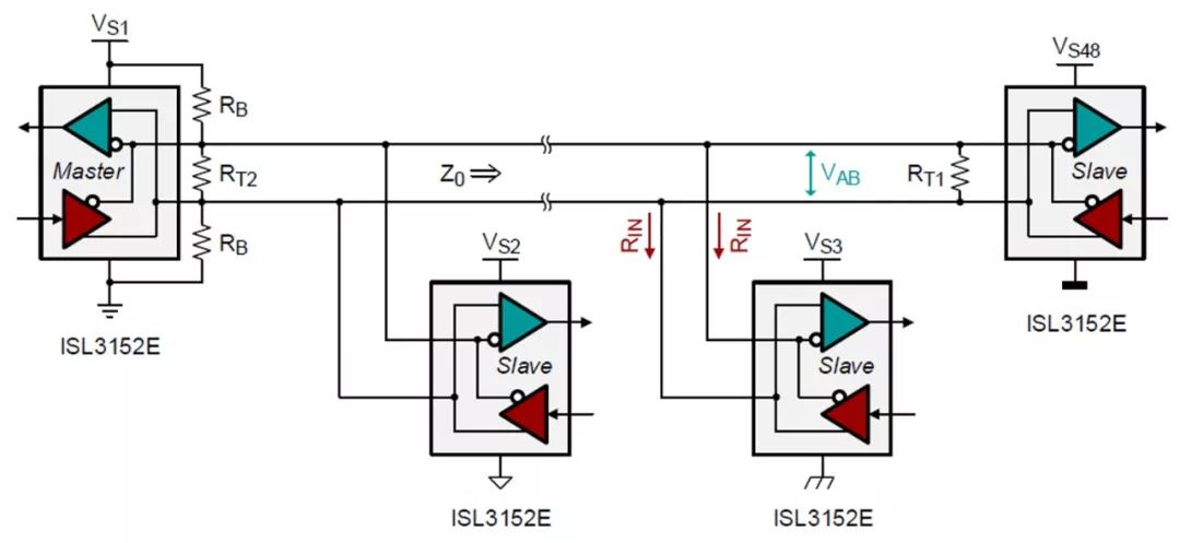
Figure 1 Suitable for short to medium bus distance communication safety and trouble-free bias resistor network
This article will help system engineers design a successful communication safe and trouble-free bias network. By providing a calculation formula, you can help calculate the resistance value and the maximum bus load allowed by the transceiver because of the safe and trouble-free one-way and two-way communication. The article will also show the ISL315x series of high-VOD transceivers, whose common mode can be connected to 60 load units (UL), far exceeding the drive capacity of 32 load units (UL) of standard transceivers.
Design of Bias Network for Safety and Failure-free Protection of Single-End Communication
For short-distance communication ≤100 meters, and when the communication is idle, the line voltage is 0.05V≤VAB≤0.3V. It is generally sufficient to set a bias circuit at one end of the bus. For simplicity, the network shown in Figure 1 is transformed into the simplified equivalent circuit of Figure 2. Please pay attention to the bias resistor RB and the termination resistors RT1 and RT2. REQ represents the equivalent input resistance of all transceivers connected to the bus.
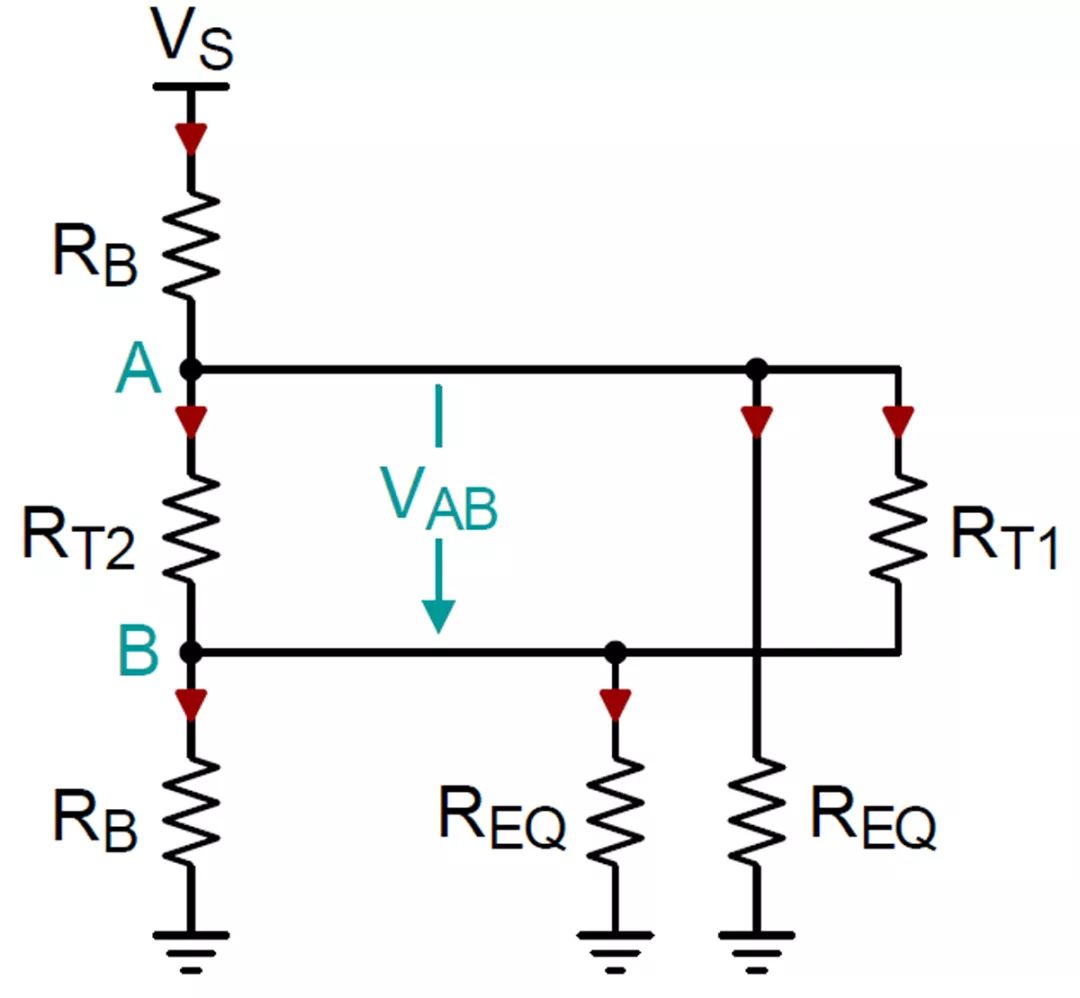
Figure 2 Simplified lumped equivalent model of the circuit
Before deriving the resistance value calculation equation, let's take a look at the conditions that must be met for line impedance matching and common mode load:
1) The termination resistance of the cable without bias network is RT1, and its resistance should match the characteristic impedance Z0 of the cable.


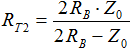
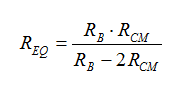
2) In order to match the line impedance during normal operation, the combination of two bias series resistors in parallel with the terminal resistor RT2 must match the characteristic impedance of the cable: Z0 = 2RB||RT2. Therefore, for a given RB value, RT2 becomes :

3) RS-485 specifies the maximum common-mode load, and a standard-compliant transceiver must be able to use 32 parallel UL drivers. The minimum common-mode resistance of a unit load (UL) is approximately 12kΩ. Therefore, the total mode load of 32 UL results in the smallest common mode resistance RCM=375Ω.
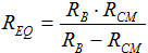
Since the bias resistor is a common-mode load outside the equivalent transceiver input resistance, the parallel value of RB and REQ must be greater than or equal to RCM: RB||REQ ≥ RCM. Therefore, for a given RB value, REQ is limited to:

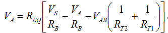
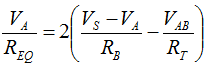
In order to find the equation for calculating RB, we determined the node currents of A and B in Figure 2, and calculated the voltages VA and VB of each line.
Node A)
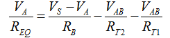
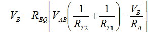
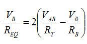
Node B)

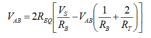
Then calculate the difference between the line voltages to obtain the differential bus voltage:
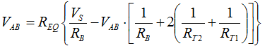

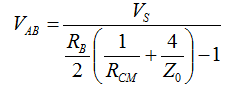
Substituting EQ.1, 2 and 3 to EQ.4 to get the final equation of the DC voltage when the communication on the cable is idle:
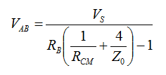

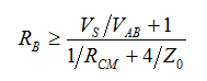
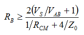
And solve the minimum bias resistance value of RB:

Common mode load
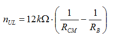
Since the communication safety and trouble-free bias circuit brings additional common-mode load, it is necessary to calculate the maximum number of transceiver units allowed on the cable after adding this load, nUL, to ensure that the bus load does not drop to RCM = 375Ω the following.
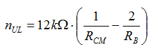
nUL is the ratio between the common mode resistance of 1 unit load (UL) and the load common mode resistance of all transceiver units on the cable: nUL =12kΩ/REQ, substituting the EQ.3 equation to obtain:

Using n×1UL, 2n×1/2UL, 4n×1/4UL or 8n×1/8UL transceivers can realize the maximum number of transceiver unit loads.
Safe and trouble-free bias circuit for both ends communication
In order to maintain a constant VAB in a long cable, a bias circuit is required at both ends of the bus. The bias resistor network at each end can compensate for the loss of the bias voltage at the other end of the cable.
Figure 3 shows a simplified equivalent circuit with a two-terminal communication safe and trouble-free bias circuit.
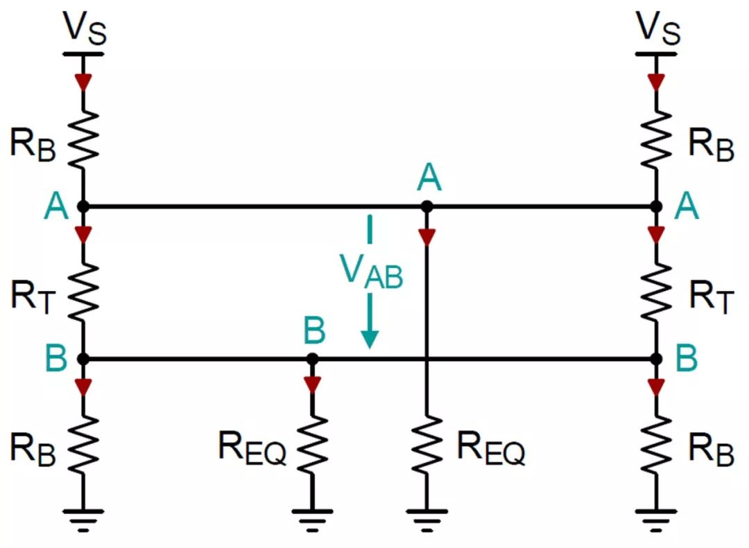
Figure 3 Simplified equivalent model of a safe and fault-free bias circuit for two-terminal communication
The requirement for terminal resistance RT is the same as RT2 of the single-ended communication safety and fault-free protection bias network, and the requirement is Z0 = 2RB||RT. Therefore, for a given RB, RT must be:


However, the conditions of the common-mode load have changed because both ends of the cable have bias resistors connected in parallel to ground. Therefore, the parallel combination of RB/2 and REQ needs to be greater than or equal to RCM: RB/2 || REQ ≥ RCM. Therefore, for a given RB value, REQ is limited to:

In order to obtain the RB equation, we determine the node currents A and B respectively. Because the bias networks are the same, they drive the same amount of current through REQ. Therefore, we must establish a current through REQ and then multiply it by 2 to determine the VAB in the middle of the bus.
Node A)
Node B)
Solve the node currents VA and VB of each line voltage and calculate the difference between them to obtain the differential bus voltage:

Bring EQ.8 and 9 into EQ.10 to get the final equation of VAB:

And solve RB to get the required minimum bias resistance value:

When using RB, the maximum number of transceiver unit loads can now be calculated in the following way:

Note that because the RB value of the two-end communication safe and fault-free bias circuit is twice the RB value of the single-end communication safe and faulty bias circuit, the nUL for the two applications is still the same.
Calculation example
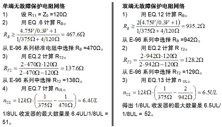
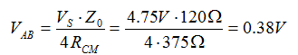
In the following example, we have calculated the bias resistance values ​​for single-ended communication without failure and two-end communication without failure. Taking long-line and short-line communication into consideration, the matching impedance is set to Z0 = 120Ω. In this example, ISL8487E bus transceiver is used. This device is a 1/8 UL transceiver with a minimum supply voltage of Vs = 4.75V. The maximum receiver input threshold is 200mV, assuming the noise tolerance is 100mV, so when the communication is idle, the line voltage VAB = 300mV is required.
RS-485 transceiver selection
For the following two reasons, choosing the best transceiver with sufficient anti-noise and output drive capability is very important for a robust cable-to-cable communication design.
1) When the bus is not actively driven, even in an environment with severe interference, there should be enough noise margin to prevent the receiver from triggering falsely.
2) During normal data transmission, the transmitting end must have enough ability to drive the common mode load increased by the communication safe and trouble-free bias resistance, and still provide a signal with sufficient noise margin for the remote transceiver.
For example, the first-generation ISL8487E device has a positive receiver input threshold of VIT-max = 200mV. Adding only a small noise margin of 50mV by biasing will result in VAB = 200mV + 50mV = 250mV.
Compare it with the second-generation transceiver (such as the ISL83082E with full fault protection). Regardless of whether the receiver input is floating (bus disconnected) or shorted (bus shorted or idle), its receiver output will go high.
The full fault protection function is achieved by shifting the maximum input threshold to a slightly negative level, in this case the level is -50mV. In order to provide the same 50mV noise margin, a VAB of 0V is sufficient to eliminate the need for a safe and trouble-free bias circuit for external communications. When there is no bias circuit, all 32 unit loads are available for the bus transceiver.
In modern industrial applications with high electrical noise pollution, industrial networks (such as PROFIBUS) use a safe and trouble-free bias circuit for communication at both ends to ensure that the bus voltage is 0.6V or higher when the bus is idle. Such a high VAB level requires the resistance of the bias resistors to be so low that their combined value drops far below the minimum common-mode resistance of 375Ω. When this happens, the calculation result of nUL will be negative. In fact, the maximum VAB can be calculated by setting RB/2 = RCM in EQ.12 (when nUL = 0).
Therefore, communications that support high VAB levels require transceivers with better performance. Compared with standard compatible transceivers, they provide higher differential and common-mode drive capabilities.
Renesas Electronics' ISL315x product series of high VOD transceivers can meet these needs. These devices can drive up to 8 120Ω termination resistors in parallel with a minimum differential output of VOD-MIN = 1.5V (see Figure 4), and can drive more than 60 DC units in the common mode voltage range of -7V to +12V Load, the minimum VOD is 2.4V (see Figure 5).
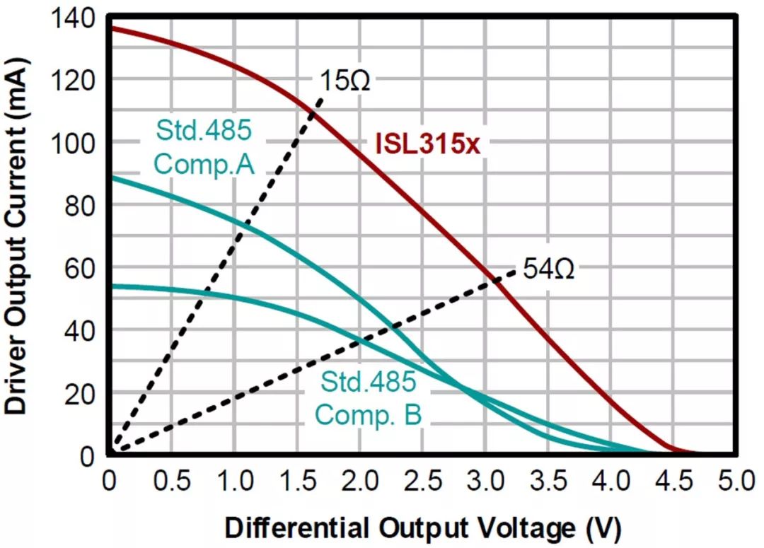
Figure 4 Differential output drive capability: ISL315x vs. standard RS-485 transceiver
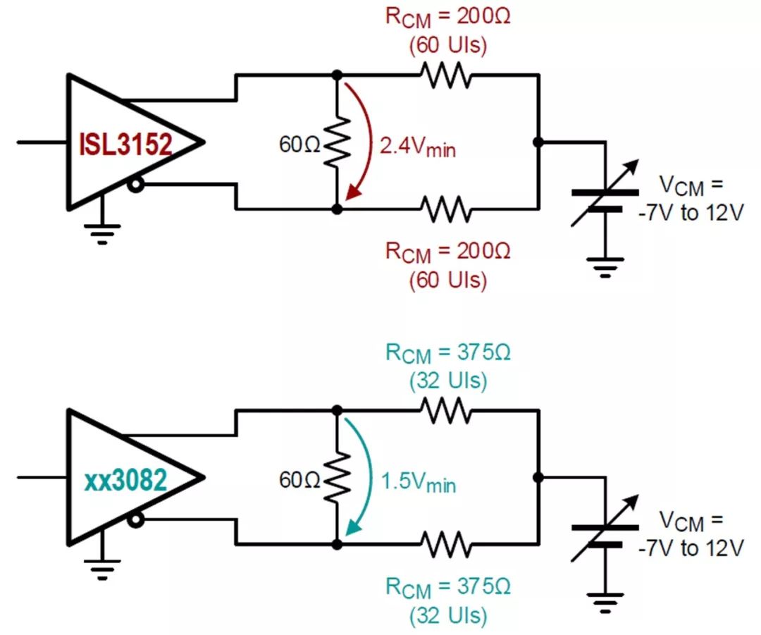
Figure 5 Common-mode output drive capability: ISL315x vs. standard RS-485 transceiver
ISL315x's excellent output drive capability also has enhanced noise immunity for the longest-distance bus transceiver, and can achieve twice the common-mode load compared with standard RS-485 transceivers.
Table 1 lists the resistance values ​​of the single-ended and two-ended communication safe and trouble-free bias networks, and compares the unit load and noise tolerance of the two available standard transceivers ISL8487 and ISL83082 and the high VOD transceiver ISL3152.
Table 1 Comparison of bias resistance, unit load and noise tolerance of standard and high VOD transceivers
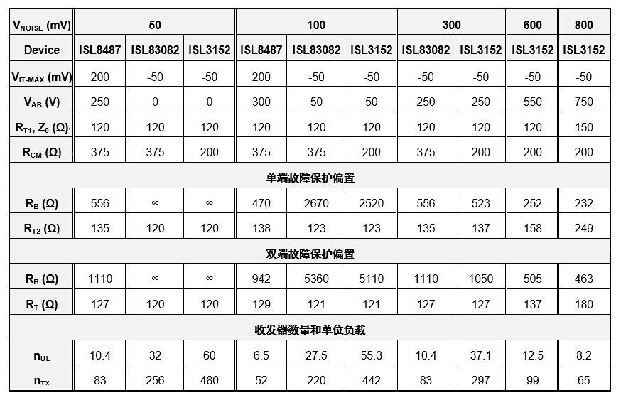
Transceivers with 200mV input thresholds, such as ISL8487, only allow up to 100mV of idle bus noise tolerance. Beyond this range, higher VAB requires a very low bias resistor value, so that the resulting number of transceiver unit loads will become negative.
A transceiver with complete communication safety and trouble-free, such as ISL83082, requires only a very low VAB value because its negative input threshold is -50mV. This allows higher bias resistance values ​​and a greater number of transceivers on the bus. However, these two transceiver types only have a standard drive capability of up to 32 unit loads, and their general standard noise tolerance and a small number of low transceiver support are difficult to use in environments with severe interference.
In sharp contrast, the ISL3152 with high VOD can easily drive more than twice the number of transceivers under moderate noise levels, and can still support up to 100 transceivers under a noise tolerance of 600mV. In order to achieve higher noise tolerance, it is necessary to increase the characteristic impedance of the cable. In PROFIBUS Z0 = 150Ω, so RT and RB can be higher values ​​to reduce the common mode load of the bias network.
in conclusion
Adding a fault protection bias network can ensure that the network nodes can still operate stably when the bus is idle. In addition, during normal data transmission, the common-mode load caused by the bias resistor must be actively driven by the driver. The high noise tolerance required by industrial networks requires low bias resistor values, and its common-mode load can overburden the drive capability of standard RS-485 transceivers. The ISL315x series of large output voltage swing transceivers can solve this problem, which can drive up to eight 120Ω termination resistors and more than 60 DC unit loads. Combined with the equations provided in this article, these transceivers simplify and speed up the design of fail-safe bias networks.
The so-called portable projector, also known as pocket projector, mainly through the 3M LCOS RGB three-color projector and decoding technology, the traditional huge projector is compact and portable, making the projection technology closer to life and entertainment.
Advantages compared with traditional projectors:
1. Small size, light weight, easy to carry.
2. Low calorific value and low noise.
3. The price is relatively cheap.
4. Most models support wireless connection through software projection.
Applicable fields:
1. Replace some functions of TV: some machines can have built-in CMMB function, or can be directly connected to the set-top box to put TV, which can be used as a 21-inch TV during the day and a 60-100-inch TV at night (Note: Because of lumen and resolution issues, lumens during the day If the degree is not enough, it must be projected at a close distance) to achieve the effect of home theater; it is convenient to move and break through the traditional film and television space. Even if you are on the mountain, you can also share today's TV series, movies, and MTV with your lover.
2. Business trip: Portable projectors are easy to carry because of their small size and light weight. When you need to display computer content or mobile phone content, you only need to connect the portable projector to achieve the demonstration effect.
3. Private space: For dormitory beds or small private spaces, in the absence of a computer, you can use a portable projector to project the content of your mobile phone to watch video pictures, etc., without staring at the mobile phone at close range.
portable projector mini,portable projector 1080p,portable projector camping,portable projector with speakers,portable projector for camping
Shenzhen Happybate Trading Co.,LTD , https://www.happybateprojectors.com