The regulated power supply generally consists of three parts: a transformer, a rectifier, and a voltage regulator. It is an electronic device that can provide a stable AC power or DC power supply for the load. Let's take a look at the role and working principle of the regulated power supply.
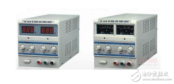
Introduction to regulated power supplyStabilized voltage supply is an electronic device that can provide stable AC or DC power to the load, including AC regulated power supply and DC regulated power supply.
When the grid voltage or load appears to fluctuate instantaneously, the regulated power supply compensates the voltage amplitude with a response speed of 10-30ms, which makes it stable within ±2%.
The function of the regulated power supply is to increase the amplification link, improve the stability, and make the output voltage adjustable; use the composite pipe as the adjustment tube to increase the output current; increase the protection circuit to make the power supply work safely and reliably.
The role of the regulated power supply has the following specific aspects:
Multi-functional comprehensive protection:
In addition to the most basic stable voltage function, the regulator should have overvoltage protection (+10 over output voltage), undervoltage protection (-10 below output voltage), phase loss protection, and short-circuit overload protection. Protective function.
Sharp pulse suppression (optional):
The power grid sometimes has sharp pulses with a very high amplitude and narrow pulse width, which can break down electronic components with low withstand voltage. The anti-surge component of the regulated power supply is very effective in suppressing such spikes.
Isolated Conductive EMI Electromagnetic Interference (optional):
CNC equipment mostly uses AC/DC rectification + PFC high-frequency power factor correction, which has certain interference and strict requirements for interference sources. The filter component of the regulated power supply can effectively isolate the interference of the power grid to the equipment and also effectively isolate the interference of the equipment to the power grid.
Lightning protection (optional): The lightning protection capability that should be provided.
With a regulated power supply, the input voltage can be kept as stable as possible, and the voltage of the power supply output is kept constant, so that the machine is not easily damaged due to voltage instability, which is the role of the regulated power supply.
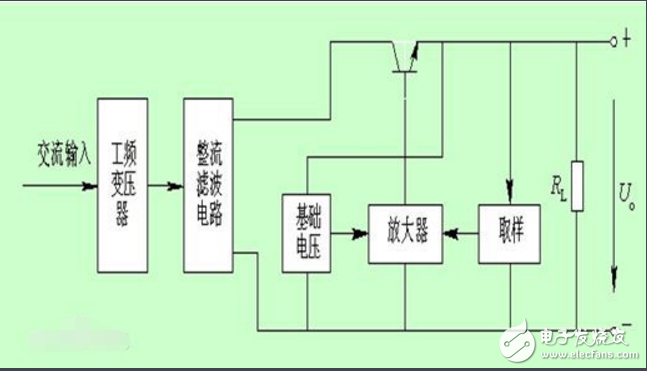
Basic working principle of regulated power supplyThe power frequency AC power supply is stepped down, rectified and filtered by the transformer to become a stable DC power. The rest of the figure is the control part that performs voltage regulation and achieves regulation. After the power supply is connected to the load, the output voltage is obtained through the sampling circuit, and the output voltage is compared with the reference voltage. If the output voltage is less than the reference voltage, the error value is amplified by the amplifying circuit and sent to the input end of the regulator, and the output voltage is increased by the regulator adjustment until it is equal to the reference value; if the output voltage is greater than the reference voltage, the regulator is passed Reduce the output.
The voltage regulator circuit is composed of =l2V power supply circuit, voltage detection control circuit and overvoltage protection. As shown in Figure 5-51, the l2V power supply circuit consists of the W4 and W5 windings of the voltage regulating transformer T and the rectifier diodes VDl-VD4 and the filter capacitor C1. And C2 composition. The voltage detection control circuit is composed of a resistor R-R7, a potentiometer RP1, Rm, a Zener diode VS, capacitors C3, C4, and an operational amplifier integrated circuit IC (Nl-N3). The overvoltage protection circuit is composed of N3 inside the IC, transistor V3, resistor Rl2, and relay K. The piezoelectric regulating circuit resistor R8-R11, the transistors V1, V2, the direct current motor M, the sliding contact and the W1 - W3 winding of the T are composed. When the large end of the AC voltage regulator is connected to the mains, an induced voltage is generated on the W4 and W5 windings of T. The voltage is rectified by VDl-VD4 and filtered by Cl and C2 to provide an unstable working voltage of IC12 and V1, V2, etc. The +l2V voltage has other effects. After Rl-R3 partial voltage and VS voltage regulation, the reference voltage is provided for the inverting input terminals of Nl-N3 respectively; the working power supply is provided for K and V3 of the overvoltage protection circuit; after being divided by R4, RP2 and R6, The detection voltage is supplied to the non-inverting input terminals of N1 and N2; after being divided by R7, RP1, and R5, the detection voltage is supplied to the non-inverting input terminal of N3.
Nl-N3 compares the detection voltage of the large-phase positive-transistor with the reference voltage of the large-end inverter, and uses the generated error voltage to control the automatic voltage regulation circuit.
When the mains voltage is normal, the output voltages of N1 and N2 are OV, Vl and V2 are both in the off state, and the motor M does not work.
When the mains voltage is low, Nl and N2 output low level, so that V2 is turned on, Vl is turned off, M is rotated counterclockwise, and the sliding contact is driven by the sliding wall arm to contact with the voltage tap corresponding to T (W of T1) A total of 21 voltage taps are set in the W2 winding, and the voltage adjustment range of each gear is 5V. The output voltage is boosted by the W2 winding of T. When the output AC voltage rises to 220V, V2 is turned off and M stops. When the mains voltage is high, Nl and N2 both output a high level, so that Vl is turned on, V2 is turned off, M is rotated clockwise, and the sliding contact is moved by the sliding arm to contact the voltage tap corresponding to T, through T Wl windings to reduce the output voltage. When the output AC voltage drops to 220V, Vl is turned off and M stops. When the mains voltage is higher than 260V, N3 outputs a low level because the voltage of the positive phase input terminal is higher than the voltage of the inverting input terminal, so that V3 is cut off, K is released, and the output circuit of the normally closed contact is connected to the AC voltage. . When the mains voltage is 160-260V, N3 outputs a high level because the voltage of the positive phase input terminal is lower than the voltage of the inverting input terminal, so that V3 is turned on, K is pulled in, and its normally closed contact is disconnected, thereby ensuring the load. (Electrical appliances) will not be damaged by overvoltage.
Power supply maintenance1. After the power supply is used for a period of time, the indication circuit should be approved. The calibration method can be adjusted by comparing the external voltmeter with the ammeter and the on-board indicating instrument; (voltage and current indication calibration respectively) for approval. However, it should be noted that since the chassis is made of steel plate structure, a small amount of reading will be caused after the cover is closed. After observing the range, the remaining amount can be adjusted during the startup adjustment.
2. Always check that the power cord wiring is loose and the interior is cracked.
3. Check if the binding posts are loose and the screws inside and outside the chassis are secure.
4. When cleaning the chassis panel and the cover, it is forbidden to use organic solvents or detergents for descaling. Use a neutral soap wave to clean with a soft rag and wipe dry.
5. The instrument should be kept clean and placed vertically.
6. If the instrument fails during use:
a No output voltage: Check if the power switch is connected, the fuse is intact, check the circuit for short circuit.
b The output voltage is too high: Check if the adjustment tube is broken.
C output voltage is unstable: Check if the reference voltage is stable.
d Output current is not enough: Check if the adjustment camp burns open circuit and the load is too heavy.
Network Accessories, Network Products, Network Items, Network Equipment, Internet Accessories
Chinasky Electronics Co., Ltd. , https://www.cctv-products.com