Transistor, full name should be a semiconductor transistor, also known as bipolar transistor, transistor, is a semiconductor device to control the current, its role is to amplify the weak signal into a large amplitude of the electrical signal, also used as a non-contact switch Is the core component of the electronic circuit.
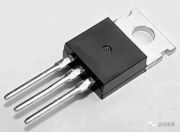
The triode is to make two PN junctions on a semiconductor substrate with short distances. The two PN junctions divide the whole semiconductor into three parts. The middle part is the base area and the two sides are the emitter area and the collector area. The arrangement is PNP. And NPN two.
1
Transistor works
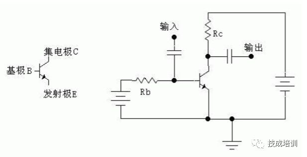
The transistor is a current amplifier device and has three poles, called collector C, base B, and emitter E, respectively. Divided into two kinds of NPN and PNP. We use the common emitter amplification circuit of the NPN transistor as an example to illustrate the basic principle of the triode amplification circuit.
A current amplification
The following analysis is only for NPN type silicon transistors. As shown in the above figure, we refer to the current flowing from the base B to the emitter E as the base current Ib; the current flowing from the collector C to the emitter E is called the collector current Ic. The directions of these two currents flow out of the emitter, so an arrow on the emitter E indicates the direction of the current.
The amplification effect of the triode is that the collector current is controlled by the base current (assuming that the power supply can provide sufficient current to the collector), and a very small change in the base current causes a large change in the collector current, and The change satisfies a certain proportional relationship: the change in the collector current is β times the change in the base current, that is, the current change is amplified by β times, so we call β the amplification of the transistor (β is generally much larger than 1, for example Ten, a few hundred).
If we add a changing small signal between the base and the emitter, this causes a change in the base current Ib, and the change in Ib is amplified, resulting in a large change in Ic. If the collector current Ic flows through a resistor R, then according to the voltage calculation formula U=R*I, the voltage on the resistor will change greatly. We take the voltage on this resistor and we get the amplified voltage signal.
Second, the bias circuit
When a triode is used in an actual amplifying circuit, it is also necessary to add a suitable bias circuit.
There are several reasons for this:
(1) First, due to the non-linearity of the transistor BE junction (equivalent to a diode), the base current must be generated after the input voltage is large enough (for the silicon tube, 0.7V is often used). When the voltage between the base and emitter is less than 0.7V, the base current can be considered as zero. However, the actual signal to be amplified is often much smaller than 0.7V. If no bias is applied, such a small signal will not be enough to cause the change of the base current (because less than 0.7V, the base current is 0).
If we put a suitable current on the base of the transistor in advance (called the bias current, the resistor Rb in the figure above is used to provide this current, so it is called the base bias resistor), then when a small When the signal is superimposed on this bias current, the small signal will cause a change in the base current, and the change in the base current will be amplified and output at the collector.
(2) Output signal range requirements. If no bias is applied, then only those added signals will be amplified and the reduced signal will be ineffective (because the collector current is zero when there is no bias, it cannot be reduced any more). . With the bias, the collector is given a certain amount of current in advance. When the input base current becomes smaller, the collector current can be reduced. When the input base current increases, the collector current increases. Such reduced signal and increased signal can be amplified.
Third, the switch effect
Let's talk about the transistor saturation. In the graph like the above, because it is limited by the resistance Rc (Rc is a fixed value, then the maximum current is U/Rc, where U is the supply voltage), the collector current cannot be increased indefinitely. When the base current increases, the collector current does not increase, and the transistor enters saturation.
The criterion for judging whether a transistor is saturated is: Ib*β>Ic. After entering the saturation state, the voltage between the collector and the emitter of the transistor will be very small. It can be understood that a switch is closed. In this way, we can use a triode as a switch: when the base current is 0, the triode collector current is 0 (this is called the transistor cut-off), which is equivalent to switch off; when the base current is so large that the triode saturates When the switch is closed. If the triode works mainly in cut-off and saturation, then such triodes are generally called switches.
Fourth, work status
If we replace the resistor Rc with a light bulb in the above figure, when the base current is 0, the collector current is 0 and the lamp is off. If the base current is large (greater than the current flowing through the bulb divided by the transistor's amplification β), the triode will saturate and the switch will close and the bulb will light up.
Since the control current only needs to be a little larger than one-sixth of the bulb current, a small current can be used to control the on/off of a large current. If the base current slowly increases from 0, the bulb's brightness will also increase (before the triode is not saturated).
For PNP triodes, the analytical method is similar. The difference is that the direction of the current is exactly the opposite of the NPN, so the direction of the arrow above the emitter is also reversed - it becomes inward.
2
Detecting the mouth of a transistor
The determination of the transistor type and the pins of the transistor is a basic skill for beginners of electronic technology. In order to quickly grasp the method of measurement, there are four sentences: "Three reversed, looking for the base; PN junction, fixed tube type; Big deflection; unpredictable, moving mouth."
One, three reversed, looking for the base
The transistor is a semiconductor device containing two PN junctions. According to the different connection modes of the two PN junctions, they can be divided into two types of transistors: NPN type and PNP type.
Test the triode to use the multimeter's ohmic block and select the R × 100 or R × 1k range. The red meter pen is connected to the cathode of the battery in the watch, and the black meter pen is connected to the anode of the battery in the watch.
Assume that we do not know whether the transistor under test is an NPN or PNP type, and it is not clear which electrode is used for each pin. The first step in testing is to determine which pin is the base. At this time, we took two electrodes (such as the two electrodes are 1, 2), with a universal meter and two pens to reverse the measurement of its positive and negative resistance, observe the deflection angle of the hands; then, take another 1 , 3 two electrodes and two electrodes 2, 3, respectively, reverse their resistance to measure the positive and negative, observe the deflection angle of the hands. In these three reversal measurements, there must be two measurements similar to each other: that is, the deflection of the hands in the reversal measurement is large at one time, and the deflection is small at one time; the remaining one must be the deflection angle of the pointer before and after the reversal of the measurement is small, this time the untested one The pin is the base we are looking for.
Second, PN junction, fixed tube type
After finding the base of the triode, we can determine the conductivity type of the tube based on the direction of the PN junction between the base and the other two electrodes.
Touch the multimeter's black test lead to the base, and the red test lead touches any of the other two electrodes. If the deflection angle of the meter pointer is large, the measured transistor is an NPN type tube; if the deflection angle of the meter pointer is small, The tested tube is a PNP type.
Third, the arrow, deflection
Find the base b, the other two electrodes which is the collector c, which is the emitter e? At this time we can determine the collector electrode c and emitter e by measuring the penetration current ICEO.
(1) For NPN triodes, use the black and red pens of the multimeter to invert the positive and negative resistances Rce and Rec between the two poles. Although the deflection angles of the multimeter pointer are small in both measurements, observe carefully. There will be a slightly larger deflection angle. At this time the current flow must be: black pen → c pole → b pole → e pole → red pen, the current flow is exactly in line with the arrow in the triode symbol (“shun arrowâ€), so At this point, the black meter pen must be connected to the collector electrode c, and the red meter pen must be connected to the emitter electrode e.
(2) For PNP type transistors, the principle is also similar to NPN type, the current flow must be: black table pen → e pole → b pole → c pole → red pen, its current flow is also in line with the direction of the arrow in the transistor symbol, Therefore, the black pen must be connected to the emitter e, and the red pen must be the collector c.
Fourth, can not measure, move mouth
If the deflection of the pointer is too small and difficult to distinguish due to the two measurements before and after inversion, it is necessary to “move the mouthâ€.
The specific method is: in the "shun arrow, deflection big" in the two measurements, with two hands, respectively, pinching the junction between the two table pens and pins, with the mouth containing (or with the tongue against) the base electrode b, still The collector electrode c and the emitter electrode e can be distinguished using the "swift arrow, large deflection" discrimination method. In which the human body acts as a DC bias resistor, the purpose is to make the effect more pronounced.
3
Common transistor
There are so many commonly used transistors, the most available on the market, the use of the largest, the price is relatively cheap pipe (for reference only oh).
(1), 2n3904, 2n3906
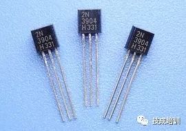
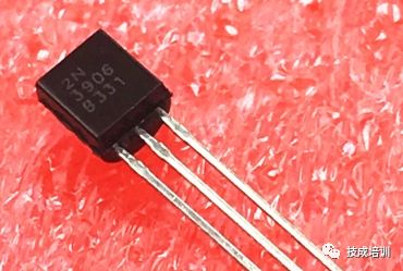
2n3904 represents an N-type transistor, and 2N3906 is a p-type transistor. This is the transistor that we use most for the control signal in designing the circuit. The main feature is the speed is particularly fast! Equivalent to the switch we often say! When we are designing the control part of the circuit, we only care about signal processing. In this case, we only need low-power triplex transistors such as 2n3904 and 2n3906. Faster speeds The greatest benefit in the control process is the very low latency.
The second feature is that the price is particularly cheap. Generally, like this one is two to three cents. It is particularly cheap. It costs a couple of cents to add up. If you use an unpopular third tube, it's a price. It will take a few cents, which is a multiple of the relationship, it is certainly a choice of cost-effective.
The third point to pay attention to 2n3904, 2n3906 generally the maximum current is 200mA, that is, its ability to pass the maximum current is 200mA, it is best to design it to less than 200mA.
(2), 2n2222, 2n2907
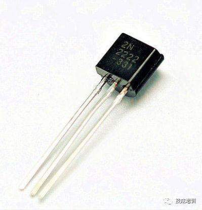
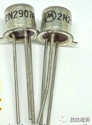
2n2222, n-type tube, which is characterized by a relatively large current capacity, about 500mA. The corresponding p-type is 2n2907. If we want to pass more current, this kind of pipe is also used more often.
(3), 8050, 8550
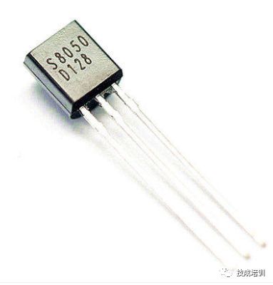
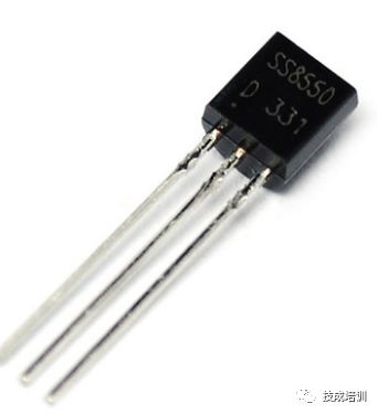
The 8050 is an n-tube and the 8550 is a p-tube. These two tubes are also commonly used by many companies. Their current capability is normally at 500mA, and its maximum current can reach 1.5A. However, the speed of this pipe is slower than the two before.
Absolute rotary Encoder measure actual position by generating unique digital codes or bits (instead of pulses) that represent the encoder`s actual position. Single turn absolute encoders output codes that are repeated every full revolution and do not output data to indicate how many revolutions have been made. Multi-turn absolute encoders output a unique code for each shaft position through every rotation, up to 4096 revolutions. Unlike incremental encoders, absolute encoders will retain correct position even if power fails without homing at startup.
Absolute Encoder,Through Hollow Encoder,Absolute Encoder 13 Bit,14 Bit Optical Rotary Encoder
Jilin Lander Intelligent Technology Co., Ltd , https://www.jllandertech.com