The pace of China's manufacturing industry is growing faster and faster. The number of industrial robots used in Chinese factories is increasing. To become an industrial robotic technical talent, the internal structure of industrial robots must be understood. Let me introduce the general industrial robots. structure.
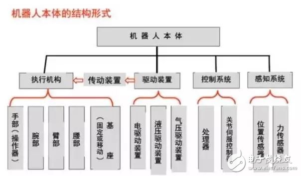
First, the robot drive device
Concept: A transmission that is mounted to each joint, ie the degree of freedom of motion, in order to operate the robot.
Function: Provide the motive force for the movement of various parts of the robot and each joint.
Drive system: It can be a hydraulic drive, a pneumatic drive, an electric drive system, or an integrated system that combines them; it can be driven directly or indirectly via mechanical transmissions such as timing belts, chains, trains, harmonic gears, etc. .
1. Electric drive device
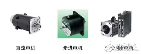
The electric drive has a simple energy source, a wide range of speed changes, high efficiency, and high speed and position accuracy. However, they are often associated with a reduction gear, and direct drive is more difficult.
The electric drive can be divided into direct current (DC), alternating current (AC) servo motor drive and stepper motor drive. DC servo motor brushes are prone to wear and are prone to sparks. Brushless DC motors have also become more widely used.
The stepper motor drive is mostly open-loop control, the control is simple but the power is not large, and it is mostly used in low-precision low-power robot systems.
Check the following before electric power-on:
1) Whether the power supply voltage is suitable (overvoltage is likely to cause damage to the drive module); For the +/- polarity of the DC input, it must not be connected incorrectly. Is the motor model or current setting value on the drive controller appropriate? Too big).
2) The control signal line is firmly connected. It is best to consider the shielding problem in the industrial field (such as using twisted pair).
3) Do not connect the wires that need to be connected at the beginning, only connect to the most basic system. After running well, connect them step by step.
4) Be sure to find out the grounding method, or use the floating.
5) Closely observe the state of the motor within half an hour of starting operation, such as whether the motion is normal, sound and temperature rise, and immediately stop the adjustment after finding the problem.
2, hydraulic drive
This is done by a high-precision cylinder and piston, which is linearly moved by the relative movement of the cylinder and the piston rod.
Advantages: The power is large, and the speed reducing device can be directly connected with the driven rod member, and the structure is compact, the rigidity is good, the response is fast, and the servo drive has high precision.
Disadvantages: Need to add hydraulic source, easy to produce liquid leakage, not suitable for high and low temperature occasions, so hydraulic drive is currently used for super power robot systems.
Choose the right hydraulic fluid. Prevent solid impurities from mixing into the hydraulic system and prevent air and water from invading the hydraulic system. The mechanical operation should be gentle and smooth, avoiding roughness, otherwise the impact load will be generated, causing frequent mechanical failures and greatly shortening the service life. Pay attention to cavitation and overflow noise. Always pay attention to the sound of the hydraulic pump and the relief valve during the operation. If the hydraulic pump has “cavitation†noise, it cannot be eliminated after exhausting. It should be found that the cause can be used after troubleshooting. Maintain a suitable oil temperature. The working temperature of the hydraulic system is generally controlled between 30 and 80 °C.
3, pneumatic drive
The air-driven structure is simple, clean, sensitive, and has a cushioning effect. However, compared with the hydraulic drive device, the power is small, the rigidity is poor, the noise is large, and the speed is not easy to control, so it is often used for the point control robot with low precision.
(1) It has the characteristics of fast speed, simple system structure, convenient maintenance and low price. Suitable for use in medium and small load robots. However, it is difficult to implement servo control, and many of them are used in program control, such as upper and lower materials and punching robots.
(2) In most cases, it is used in medium and small robots that implement two-bit or finite point control.
(3) Control devices Most of them currently use programmable controllers (PLC controllers). In flammable and explosive situations, pneumatic logic components can be used to form the control device.
Second, linear transmission mechanism
The transmission is a key part of the connection of the power source and the moving link. According to the joint form, the commonly used transmission mechanism has a linear transmission and a rotary transmission mechanism.
The linear transmission mode can be used for the X, Y, Z direction drive of the Cartesian coordinate robot, the radial drive and vertical lift drive of the cylindrical coordinate structure, and the radial telescopic drive of the spherical coordinate structure.
The linear motion can convert the rotary motion into linear motion through the transmission components such as the rack and pinion, the screw nut, etc. It can also be driven by a linear drive motor or directly by the piston of the cylinder or hydraulic cylinder.
1, rack and pinion device
Usually the rack is fixed. The rotational motion of the gear is converted into a linear motion of the pallet.
Advantages: Simple structure.
Disadvantages: The difference is large.
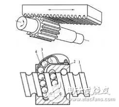
2, ball screw
The balls are embedded in the spiral grooves of the lead screw and the nut, and the balls can be continuously circulated through the guide grooves in the nut.
Advantages: low friction, high transmission efficiency, no creep, high precision
Disadvantages: high manufacturing costs and complex structure.
Self-locking problem: In theory, the ball screw pair can also be self-locking, but the self-locking is not used in practical applications, mainly because of poor reliability or high processing cost; because the diameter to lead ratio is very large, Generally, a self-locking device such as a worm gear is added.
Third, the rotating transmission mechanism
The purpose of the rotary transmission mechanism is to convert the higher rotational speed of the motor's drive source output to a lower rotational speed and obtain a larger torque. Rotary transmission mechanisms that are used more in robots include gear chains, timing belts, and harmonic gears.
1, the gear chain
(1) Speed ​​relationship
(2) Torque relationship
2, timing belt
The timing belt is a belt having a plurality of teeth that mesh with a timing pulley that also has a tooth. It is equivalent to a soft gear when working.
Advantages: no sliding, good flexibility, low price, high repeatability.
Disadvantages: There is a certain elastic deformation.
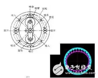
3, harmonic gear
The harmonic gear is composed of three main parts: a rigid gear, a harmonic generator and a flexible gear. Generally, the rigid gear is fixed, and the harmonic generator drives the flexible gear to rotate.
main feature:
(1) The transmission ratio is large, and the single stage is 50-300.
(2) The transmission is stable and the carrying capacity is high.
(3) Transmission efficiency is high, up to 70%-90%.
(4) The transmission precision is high, which is 3-4 times higher than the ordinary gear transmission.
(5) The return difference is small, which can be less than 3'.
(6) The intermediate output cannot be obtained, and the flexural rigidity is low.
Harmonic transmissions have been widely used in countries with advanced robotics. In Japan alone, 60% of robotic drives use harmonic drives.
The robots sent to the moon by the United States use harmonic transmissions for each joint, and one of the upper arms uses 30 harmonic transmission mechanisms.
The mobile robot "moon stalker" sent to the moon by the former Soviet Union, the eight wheels installed in pairs are driven separately by a closed harmonic drive mechanism. The ROHREN, GEROT R30 robot developed by Volkswagen AG and the VERTICAL 80 robot developed by Renault of France all adopt harmonic drive mechanism.
Fourth, the robot sensing system
1. The sensory system consists of an internal sensor module and an external sensor module to obtain meaningful information in the internal and external environmental conditions.
2. The use of smart sensors improves the maneuverability, adaptability and intelligence of the robot.
3. The use of smart sensors improves the mobility, adaptability and intelligence of the robot.
4. For some special information, the sensor is more effective than the human perception system.
Five, robot position detection
Rotating optical encoders are the most commonly used position feedback devices. Photodetectors convert light pulses into binary waveforms. The corner of the shaft is obtained by counting the number of pulses, which is determined by the relative phase of the two square wave signals.
The inductive synchronizer outputs two analog signals, the sine and cosine signals of the shaft angle. The corner of the shaft is calculated from the relative amplitudes of the two signals. Inductive synchronizers are generally more reliable than encoders, but have lower resolution.
Potentiometers are the most direct form of position detection. It is connected to the bridge and produces a voltage signal proportional to the angle of the shaft. However, the resolution is low, the linearity is not good, and it is sensitive to noise.
The tachometer is capable of outputting an analog signal proportional to the speed of the shaft. If there is no such speed sensor, the speed feedback signal can be obtained by the difference of the detected position with respect to time.
Sixth, robot force detection
The force sensor is usually mounted in the following three positions on the operating arm:
1. Install on the joint drive. The torque or force output of the drive/gearbox itself can be measured. However, the contact force between the end effector and the environment cannot be well detected.
2. It is installed between the end effector and the terminal joint of the operating arm and can be called the wrist force sensor. Typically, three to six force/torque components applied to the end effector can be measured.
3. Install on the “fingertip†of the end effector. Often, these forces have a built-in strain gauge on your finger that measures one to four component forces acting on your fingertips.
Seven, robot-environment interaction system
1. The robot-environment interaction system is a system that enables industrial robots to communicate and coordinate with devices in the external environment.
2. The industrial robot is integrated with external equipment as a functional unit, such as a manufacturing unit, a welding unit, an assembly unit, and the like. It can also be integrated with multiple robots, multiple machine tools or equipment, and multiple parts storage devices.
3. It can also be a multi-robot, multiple machine tools or equipment, multiple parts storage devices, etc. integrated into one functional unit to perform complex tasks.
Eight, human-computer interaction system
The human-computer interaction system is a device that allows an operator to participate in robot control and to communicate with the robot. The system is grouped into two broad categories: command given devices and information display devices.
Icom Radio,otorola Radio Repeater,Motorola Dmr Repeater,Motorola Uhf Repeater
Guangzhou Etmy Technology Co., Ltd. , https://www.digitaltalkie.com