Instrument failure is a problem we often encounter in our work, so what are the good ways to judge the fault and find out the problem? The following small series for you to sort out 10 methods of industrial instrument failure analysis and judgment, summed up many years of instrument maintenance experience, I hope to be helpful to everyone.

1 visual inspection
Without any test instrument, the person's senses (eyes, ears, nose, hands) are used to observe the method of finding the fault. The visual inspection method is divided into two types: visual inspection and power inspection.
The visual inspection content mainly includes:
1 Whether the instrument housing and dial glass are intact, whether the pointer is deformed or touched with the dial, whether the assembly fastener is firm, whether the position of each switch knob is correct, whether the movable part is flexible, and whether the adjustment part changes significantly;
2 Whether the connection is disconnected, whether the connectors are normally connected, whether the reed on the circuit board socket is insufficient in elasticity and poor contact. For the instrument assembled by unit combination, pay special attention to whether the connection screws of each unit board are tightened;
3 Whether the contacts of the relays and contactors are misaligned, stuck, oxidized, burnt and stuck;
4 Whether the power fuse is blown, whether the electron tube is cracked or leaked (a layer of white powder adheres to the inner wall of the tube after leaking), damage, whether the coating of the transistor casing is discolored, broken, whether the resistor is burnt, whether the coil is broken, or the capacitor Whether the outer casing is inflated, leaking or bursting;
5Whether the printed copper strip is broken, tinned, short-circuited, whether the solder joints of each component are good, and there are no soldering, missing soldering or desoldering;
6 Whether the arrangement and wiring of each component are skewed, misaligned, dropped, and touched.
The boot check mainly includes:
1 Whether the power indicator light, each tube and other light-emitting components in the machine are powered on;
2 There is no high-voltage ignition, discharge or smoke in the machine;
3 with or without vibration and humming, rubbing, and impacting;
4 transformers, motors, power amplifier tubes and other easy-to-heat components and resistance, integrated block temperature rise is normal, whether there is a hot phenomenon;
5There is no special smell in the machine, such as the resistance of the transformer due to the burning of the insulation layer, the oscillating smell of the oscillating tube is caused by the high-voltage leakage of the oscillating tube;
6 Whether the mechanical transmission part is working normally, whether there are gears that are not well meshed, stuck and severely worn, slipped and deformed, and the transmission is not working.
Visual inspection must be very careful and careful not to be careless. Only gently sway when inspecting components and wiring, do not use excessive force to prevent breakage of components, wiring and printed circuit board copper foil. Do not leave the power switch when the power is turned on. If it is abnormal, it should be turned off in time. Pay special attention to personal safety and absolutely avoid touching both hands with live equipment. The large-capacity filter capacitor in the power circuit has a charging charge in the circuit to prevent electric shock.
2 investigation method
Through the investigation of the fault phenomenon and its development process, the method of judging the cause of the fault is analyzed. Generally have the following aspects:
1 use before the failure occurred and whether there are any precursors;
2 Whether there is any fire, smoke or abnormal smell when the fault occurs;
3 power supply voltage changes;
4 external conditions such as overheating, lightning, humidity, and collision;
5 Whether it is interfered by external strong electric and magnetic fields;
6 Whether there is improper use or misuse;
7 failures under normal use, or failures after repairing replacement components;
8 What faults and repairs have occurred before?
Use the investigation method to overhaul the faults, investigate and understand that it is necessary to be thorough and careful, especially to verify the reflection of the on-site personnel, and do not rush to open the inspection. Maintenance experience shows that many of the respondents' responses are incorrect or incomplete, and many problems that require no maintenance can be found through verification.
3 breaking method
Disconnect the suspected part from the whole unit or unit circuit to see if the fault can disappear, thus determining the method of the fault.
After the instrument fails, first determine the possibility of the fault. In the area of ​​the fault range, disconnect the suspicious part of the circuit to determine if the fault occurred before or after disconnection. If the power-on check finds that the fault disappears, it indicates that the fault is mostly in the disconnected circuit. If the fault still exists, further disconnection and split inspection is performed, and the suspect is gradually eliminated, and the fault range is narrowed until the real cause of the fault is detected.
The open circuit method is especially convenient for unitized, combined, and plug-in instrumentation fault detection, and is also effective for some short-circuit faults with excessive current. However, it is not suitable to use a closed system loop or a direct coupled circuit structure in which the overall circuit is a large loop.
4 short circuit method
Temporarily short-circuit a certain level of circuit or component suspected of failure, and observe whether there is any change in the fault state to determine the fault location.
When the short circuit method is used to check the multi-stage circuit, if a certain level of circuit or component is temporarily shorted, if the fault disappears or decreases significantly, it indicates that the fault is before the short-circuit point, and the fault does not change after the short-circuit point. If the output of a certain stage is not normal, the input end of the stage is short-circuited. If the output potential is normal, the circuit of this stage is normal.
The short-circuit method is also commonly used to check whether the components are normal. For example, the base and emitter of the crystal triode are short-circuited with tweezers, and the change of the collector voltage is observed to determine whether the tube has amplification. In the TTL digital integrated circuit, the short circuit method is used to judge whether the gate circuit and the trigger can work normally. The thyristor control electrode and the cathode are short-circuited to determine whether the thyristor is inoperative or the like. In addition, some instruments (such as electronic potentiometer) input terminals can be short-circuited, and the meter indicates changes to determine whether the meter is interfered.
5 replacement method
A method of determining the fault at a certain location by replacing certain components or boards.
Replace the suspected components with the same specifications and good performance components, and then conduct the power test. If the fault disappears, you can determine the suspected component is the fault. If the fault persists, the same alternative test can be performed on another suspect component or board until the fault location is determined.
Before you replace it, you should use a little time to analyze the cause of the failure, rather than blindly changing components. If the fault is caused by a short circuit or thermal damage, the good components on the replacement may also be damaged. If a diode burns out, it may be because the working current and reverse peak voltage of the tube are not enough. If another diode of the same type is replaced at this time, only the fault is temporarily processed and not eliminated.
In addition, the replacement of components should be cut off the power supply, not allowed to be welded while testing. When the replaced components are installed and welded, they should conform to the original welding installation method and requirements. For example, a high-power transistor and a heat sink are usually provided with an insulating sheet, so don't forget to install it. When replacing, be careful not to damage other components around you to avoid human failure.

6 Divisional Law
In the process of finding faults, the circuit and electrical parts are divided into several parts to find out the cause of the fault.
General inspection and control instrumentation circuit can be divided into three parts, namely external circuit (all circuits from the terminal of the instrument to the detection component and control actuator), power circuit (all circuits from AC power supply to power transformer), internal Circuit (all circuits except the external circuit and power supply circuit). It can be divided into several small parts in the internal circuit (according to its internal circuit characteristics and electrical component structure). The divisional inspection is based on the various parts that are divided, and the parts are inspected from the outside to the inside, from the big to the small, and by the method of the table and the inside, gradually narrowing the scope of doubt. When it is checked which part of the fault is being determined, a full inspection of this part is performed to find the fault location.
The branch inspection checks and analyzes the various parts of the instrument and the instrument in order. Although it is more organized, the inspection time is long. In the inspection, the key points are often not caught and a lot of time is wasted. This method is suitable for the maintenance personnel with less maintenance experience, less familiar with the instrumentation fault phenomenon, and the fault is more complicated.
7 human body interference method
Humans in a messy electromagnetic field (including the electromagnetic field generated by the AC grid) will induce a weak low-frequency electromotive force (nearly tens to hundreds of microvolts). When a person touches certain circuits of the instrument, the circuit will reflect. Using this principle, some faults of the circuit can be easily judged.
Use the human body interference method to pay attention to the environment. If the electrical equipment and lines are relatively small and the basement and part of the steel building are small, the signal generated by the interference will be smaller. At this time, a long wire can be used instead of the hand to obtain a large interference signal. In addition, this method is used to check the high-voltage parts of the instrument or the instruments and instruments that are charged on the bottom plate. Be careful to ensure safety and avoid electric shock.
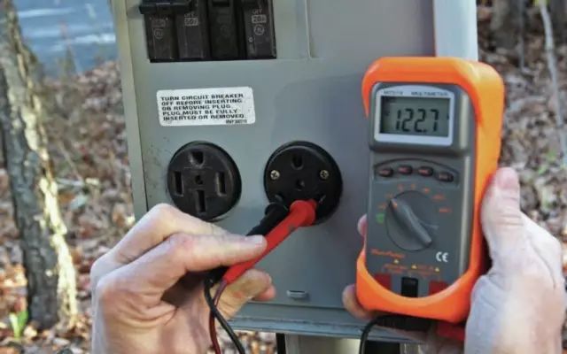
8 voltage method
The voltage method is to measure the suspect part with a proper range using a multimeter (or other voltmeter), and measure the AC voltage and the DC voltage. The measured AC voltage mainly refers to the AC supply voltage, such as AC 220V network voltage, AC voltage regulator output voltage, transformer coil voltage and oscillating voltage, etc.; DC voltage measurement refers to DC power supply voltage, electron tube, semiconductor component pole working voltage, integrated block Each lead angle is equal to the ground voltage.
The voltage method is one of the most basic methods in maintenance work, but the range of faults it can solve is still limited. Some faults, such as a slight short circuit of the coil, a broken capacitor or a slight leakage, are often not reflected in the DC voltage. Some faults, such as component short circuit, smoke, flashover, etc., must be turned off, the voltage method will not work at this time, then other methods must be used to check.
9 current method
The current method is divided into direct measurement and indirect measurement. The direct measurement is to disconnect the circuit into the ammeter and compare the current value with the data in the normal working state of the instrument to judge the fault. If you find out which part of the current is not in the normal range, you can think that this part of the circuit has a problem, at least affected. Indirect measurement does not open the circuit, the voltage drop across the resistance is measured, and the approximate current value is calculated according to the magnitude of the resistance value, which is mostly used for measuring the current of the transistor element.
The current method is more troublesome than the voltage method. Generally, the circuit needs to be disconnected and then connected to the ammeter for testing. But it is easier to fail in some cases than the voltage method. The current method and the voltage method cooperate with each other to check and judge most of the faults in the circuit.
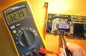
10 resistance method
The resistance check method is to check whether the input and output resistance of the instrument circuit and part of the circuit are normal with a multimeter under the condition of no power supply; whether the resistance elements are open circuit, short circuit, or whether the resistance value changes; whether the capacitor is broken down or Leakage; inductance coil, transformer with or without wire breakage, short circuit; semiconductor device forward and reverse resistance; each integrated block leads the foot to ground resistance; and roughly judge the transistor beta value; the electron tube, the oscilloscope tube has a short circuit between the poles, the filament is intact Wait.
When applying the resistance method to check for faults, the following points should be noted:
1Because there are many nonlinear components in the circuit, such as transistors, large-capacity electrolytic capacitors, etc., when the resistance between two points is measured by the resistance method, because these nonlinear components are connected, pay attention to the red and black poles of the multimeter. Sex, because the results measured by different polarities are different;
2 Avoid using Ω×1 block (large current) and Ω×10K block (higher voltage) to directly measure transistors and integrated circuit blocks with low current and low withstand voltage to avoid damage;
3 Most of the components under test in the instrumentation are implicated (series or parallel) with many other components. Therefore, in the case where the leakage is not caused by direct breakdown or the resistance is relatively large, the component to be tested is released and then inspected and measured. For components such as resistors and capacitors with only two lead wires, as long as one lead is disconnected, and for three wires such as a crystal triode, the two lead wires should be disconnected.
Copper Cooling Tube
[HIGH REFRIGERATION EFFICIENCY]Good heat dissipation and refrigeration capability,high strength at low temperature.Copper tubes are hollow,so has strong heat transfer capability.If you need refrigeration for refrigerators, freezers, air conditioners, this is a good choice
[COPPER MATERIAL]Copper refrigerator tube has the features of high temperature resistance, corrosion resistance, oxidation resistance, durability, long service life[SOFT & SHAPE CHANGEABLE]Because refrigeration copper pipe can bend and deform, they can often be made into elbows and joints. Smooth bending allows copper tubes to bend at any angle
[WIDELY APPLICATION]Refrigerator Tubing is not only used for refrigerator, freezer and air conditioner as refrigeration tubing coil, but also used as a HVAC system pipe.
Condenser Copper Tube,Copper Cooling Tube,Copper Tube Air Cooling,Copper Cooling Fin Tube
FOSHAN SHUNDE JUNSHENG ELECTRICAL APPLIANCES CO.,LTD. , https://www.junshengcondenser.com