A Simulation Model of Network Equipment Based on DEVS
Based on the analysis of the main problems faced by the current network equipment simulation modeling, the DEVS specification and its basic components are briefly introduced; taking the Ethernet switch as an example, the DEVS-based network equipment simulation modeling technology is studied Realized simulation modeling. The advantages of the network equipment modeling method are summarized, and the application prospect of this modeling method in network equipment modeling is prospected.
Keywords: discrete event simulation specification; exchange; computer simulation; simulation model
With the widespread use of distributed interactive simulation (DIS) technology, network simulation systems are developing in the direction of distributed, large-scale, and high complexity, and may be interconnected with other types of systems to form larger and more capable A simulation system that reflects the real world. Therefore, the design of the network simulation system puts forward higher requirements in terms of standardization, reliability and reusability. The current communication networks are all built on the basis of packet exchange. Therefore, the network simulation system of this communication network is a typical discrete event system. The state of the entities in the system changes at uneven discrete moments. The internal mechanism is conventional. The mathematical method is difficult to describe. In engineering practice, there is an urgent need for a formal description method that can be easily converted into a program model. The discrete event system specification states that DEVS is a formal description of a discrete event system. Based on the formalization of the general system model of system theory, a modular system description method is provided, which is beneficial to various models in complex systems. Abstraction and simulation implementation.
This article takes the Ethernet switch as an example, parses the switch model into different sub-models and coupling models based on the specification method based on DEVS, and simulates the switch model.
1 The DEVS specification states that the basic idea of ​​DEVS is to gradually decompose the system into multi-level sub-models according to function or structure. The indivisible model is an atomic model. The model composed of sub-models is called a coupling model. In the coupled model, the relationship between the sub-models is called coupling.
In the modeling and simulation of complex systems, the atomic model describes the transition of time and state, and the coupling model describes the submodels that make up it and the interconnection between the submodels and submodels. In this configuration, the atomic model is the basic system element, it is a complete, independent unit, such a model only interacts with other models through the input and output interfaces to achieve modularity. The system establishes a coupling model by connecting atomic models, and the coupling model is combined with other models to form a higher-level system. In the modeling process of complex systems, the atomic model is like a circuit element, and the coupling model is like a circuit board. Therefore, the modeler can significantly improve the efficiency and quality of the modeling project by reusing the modular model and building the simulation model in a hierarchical manner.
2 Simulation Example of Network Entity Model Based on DEVS The following uses Ethernet switches as an example to introduce in detail how to simulate it with the DEVS standardized model description method. The concept of hierarchical model structure, atomic model and coupling model will be explained.
There are four types of Ethernet switch entities, namely Layer 2 switch entities, Layer 3 switch entities, Layer 4 switch entities, and Multi-layer switch entities. Here, the layer 2 switch entity is used as an example for discussion.
First, according to the DEVS normalized model description method, a quadruple like EN = can be used to describe the switch entity. Among them, N is the name of the entity, TE is the function completed by the entity, AT is the set of attribute of the entity, AC is the set of action of the entity, S is the set of state of the entity.
EN =
Among them, N is the layer 2 switch; TE is the forwarding data; AT is AT = {switch serial number, model, version number, port number, port type, manufacturer, RAM space, ROM Moniter, Fresh / NVROM, IOS version, MAC address , Supported protocols}; AC, CT = {physical connection, power-on self-test, configuration}; S, S = {idle, busy}.
After completing the standardized description of the switch entity, let's look at the internal structure of the switch and how to complete the switch coupling model and its interface coupling model.
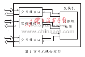
2.1 The switch coupling model and its composition are divided according to the structure. The Ethernet switch can be decomposed into n switch interfaces and an n × n switching structure. The structure is described with two sub-models of switch interface and switch unit. The hierarchical structure and input / output relationship of the Ethernet switch coupling model and sub-model are shown in Figure 1.

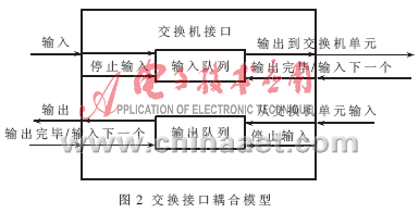
Among them, the switch interface model includes two queue atomic models for describing input and output, and the number of interfaces may vary with the switch model. According to different requirements, the sub-model of the exchange structure can be abstracted as an atomic model without further decomposition, or can be decomposed into two sub-models of the exchange network and the MAC table. The following uses the switch interface coupling model as an example to describe the definition method of DEVS in detail. The model descriptions of other parts can also be obtained by this method.
2.2 Switch interface coupling model The relationship between the switch interface coupling model and its submodels is shown in Figure 2. In order to process the data flow in and out of the network interface card model, the interface model is decomposed into two queue atom models, one for receiving data frames from the network and the other for forwarding data frames to the network. This abstraction describes the input and output of the interface as a queue model.

The DEVS of the queue model of the atomic model is described as:
queue =
among them:
X: {MAC frame, stop / response signal, done / ready signal}
S: {readytoProcess, waitforResponse, waitforReady, C}
Y: {MAC frame}
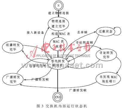
Queue as a subsystem, its control and state changes are determined by the internal operating state machine of the switch. The internal operating state machine of the switch is shown in Figure 3.

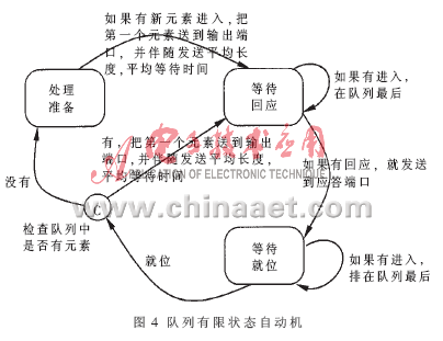
It is known from analyzing the internal operating state machine of the switch that the queue can be described using the finite automaton shown in FIG. 4.
In Figure 4, the various states of the queue, the mutual conversion relationship between them and the required trigger conditions are clear at a glance, and the internal and external transfer functions of the queue can be given as follows.

δint (e, s):
{
case phase:
state = nothing. / * never happens * /
}
δext (e, s, x):
{
case state:
readytoProcess:
case in: send 1st element on out port, send
average size,
send average wait, state = waitforResponse
waitforResponse:
case in: add to end of queue, state = waitfor
Response
response: send on reply port, state = waitfor-
Ready
waitforReady:
case in: add to end of queue
ready: state = C
C:
case true: send 1st element on out port, send
average size, send average wait, state =
waitforResponse
false: state = readytoProcess
}
λ (s):
{
output the MAC frame
}
The time advancing function ta is the time that the system maintains when no external events arrive, and it may not be defined here.
The main role of the coupling model is to clarify the connection relationship between the input and output of the model, and the switch interface coupling model can be described as follows:
SwitcherInterface = d}, {Id}, {Zid}>
X: {MAC frame, stop signal, next signal}
Y: {MAC frame}
{Md} = {queueIn, queueOut}
{Id} = {IqueueIn = {Switcher.in, SwitchStructure.next, SwitchStructure .stop},
IqueueOut = {SwitchStructure.next, SwitchStructure.stop,
outside done signal}}
{Zid} = {SwitcherInterface.in = IqueueIn. In,
SwitcherInterface.out = IqueueOut.out}
At this point, the simulation modeling of the Layer 2 switch is completed.
For the description of discrete systems, the formal methods of set theory and system theory can be used. Typical examples include differential equations, finite state machines, and discrete event models. The advantage of DEVS is to impose specific constraints on the static and dynamic structure of the system determined by each type of such model, so as to determine the decomposition method of the system. The use of DEVS description model makes discrete system simulation no longer a random, personalized artistic work [1]. In this sense, the model described by DEVS overcomes the shortcomings of other models such as poor reusability, irregularity, and poor interoperability. With the advantages of stronger standardization, certainty, and reusability, it is better solved New problems caused by the dynamic changes of network traffic, the randomness of statistical multiplexing and the expansion of the network scale.
At present, network system modeling based on DEVS is mainly focused on performance simulation, and there is relatively little research on functional simulation. Among them, the formal description is more difficult to understand is one of the reasons for this situation. In recent years, the research results in the visual modeling based on DEVS have made up for the deficiencies in this area to some extent [3].
In addition, for the network simulation system, to what level the model is abstracted, it can not only reflect the real situation relatively well, but also not generate too much calculation amount. It is an engineering practice problem worthy of in-depth study.
In summary, the simulation model of network equipment based on DEVS adopts the formal simulation modeling method of DEVS to standardize the simulation modeling of discrete systems such as network communication switches. Its accuracy and reusability are self-evident. And metaphorically. Under the trend of standardization, the simulation method based on DEVS is expected to play a more important role in network simulation and simulation.
references
[1] Huang Kedi, Zhang Jinhuai. System Simulation Technology. Changsha: National University of Defense Technology Press, 1998.
[2] Zeigler B P. Modeling and Simulation Theory. Translated by Li Yucai. Beijing: Mechanical Industry Press, 1984.
[3] Liu Zhong, Deng Su. Object-oriented visual modeling of DEVS. Computer Simulation, 2001, 18 (1).
[4] Liu Baohong, Huang Kedi. Research on the formal description specification of multi-resolution modeling based on DEVS, Journal of System Simulation, 2005 (17).
[5] Mohaemd Abd El-Salam, KhalilYonis, Abdul-Rahman Elsahfei. Fourth year project report: Building a library for parallel simulaTIon of networking protocols, Carleton University, Canada.
[6] PETRIU D, WAINER G. A library of layered queuing networks using the DEVS formalism, Proceedings of the SCS 1st Mediterranean MulTIconference on Modeling and SimulaTIon. Genoa, Italy. 2004.
Longkou Libo Insulating Material Co.,Ltd. , https://www.sdliboinsulation.com