The voltage follower, as the name suggests, is that the output voltage is the same as the input voltage, that is, the voltage amplification of the voltage follower is always less than and close to 1. The salient feature of voltage followers is that the input impedance is high and the output impedance is low. Generally speaking, it is easy to achieve an input impedance of several megaohms. The output impedance is low, usually to a few ohms or even lower.
The main reason for the phase difference at the input and outputThe reasons can be roughly divided into two types:
1. Due to the inherent characteristics of operational amplifiers
2. Due to the characteristics of the feedback loop other than the operational amplifier
Operational amplifier characteristicsFig2a and Fig2b respectively represent the voltage gain-frequency characteristic and phase-frequency characteristic of the operational amplifier. These two graphs are also in the data sheet.
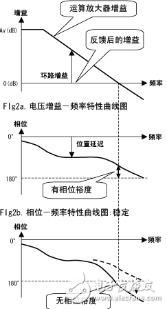
As shown in the figure, the voltage gain and phase of the operational amplifier vary with frequency. The difference between the gain of the operational amplifier and the feedback gain (0dB when using a voltage follower) is the gain of the feedback loop (feedback gain). If the feedback gain is less than 1 times (0dB), even if the phase changes by 180o and returns to the positive feedback state, the negative gain will gradually attenuate in the circuit, and theoretically will not cause oscillation.
Conversely, when the phase changes by 180o, if the loop gain corresponding to the frequency is doubled, the original amplitude will be maintained; if the loop gain corresponding to the frequency is greater than 1, the amplitude will gradually diverge. In most cases, in the process of amplitude divergence, the amplitude is limited due to the influence of nonlinear factors such as the maximum output voltage, and the oscillation state will be maintained.
For this reason, the difference between the phase corresponding to the frequency when the loop gain is 0 dB and 180o is an important factor in judging the stability of the negative feedback loop. This parameter is called the phase margin. (Fig2b.)
Unless otherwise specified, when a single amplifier is used as a voltage follower, sufficient phase margin must be maintained.
Note: Amplifiers marked in the data sheet as "recommended to use gains of 6 dB or more" cannot be used as voltage followers.
Influence of Operational Amplifier Peripheral Circuit on Feedback LoopIn practical applications, the voltage follower is not as simple as Fig. 1. The input and output are directly connected together. At least the output is connected to a load. Therefore, the influence of this load on the amplifier must be considered.
For example, as shown in Fig3., When a capacitor is connected between the output terminal and ground, a constant formed by this capacity and the output resistance of the operational amplifier causes a phase lag.
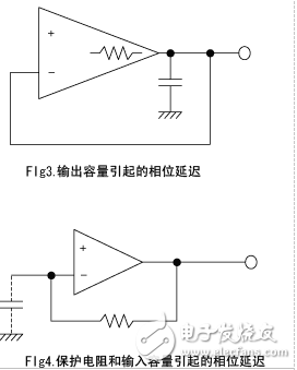
(The state shown in Fig2b. May change to the state shown in Fig2c.) At this time, the loop gain is reduced by the output resistance and C. At the same time, there is no longer a proportional relationship between phase and gain, and phase lag becomes a decisive factor, destabilizing the feedback loop, which may cause oscillation at the worst. When a capacitor is simply connected between the output terminal and ground to form a voltage follower, the stability of each operational amplifier differs.
Fig4. Possible problems for operational amplifiers that require protection resistors at the input.
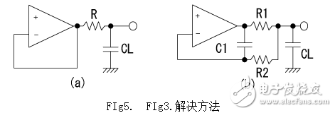
In order to solve the problems in Fig3., The methods shown in Fig5. (A) and (b) can be used. (A) Insert R in the figure to eliminate the feedback loop phase lag caused by CL. (In the high-frequency region, R appears as the load of the operational amplifier instead of CL.) (B) C1 is used to eliminate the phase lag caused by CL.
To solve the problem of Fig4., A capacitor of appropriate size can be connected in parallel with the input protection resistor. The approximate value generally referred to as the "input capacitance cancellation value" is about 10pF to 100pF.
72V Battery Pack ,Lithium Ion Battery Pack,Lithium Battery Pack,Battery Power Pack
Zhejiang Casnovo Materials Co., Ltd. , https://www.casnovo-new-energy.com