In this paper, high-brightness LED is used as the core device of the street lamp to design the street lamp monitoring system. On the scene, the street lamp current and voltage are collected from the single chip microcomputer, and then the GPRS data is transmitted through the host computer and the host computer, so as to achieve the purpose of "remote control, telemetry, and telemetry".
2 System working principle and hardware design
2.1 Overall system design
The overall structure is shown in Figure 1. The system is mainly composed of LED energy-saving control center, China Mobile GPRS network and street lamp RTU.
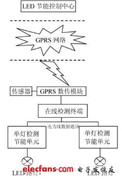
Figure 1 overall structure diagram
Among them, the street lamp monitoring center includes 3131P Modem module, street lamp monitoring RTU, online monitoring terminal control box, GPRS type module, single lamp detection controller, etc.
In this monitoring system, the controller unit is connected to the mobile GPRS wireless terminal through RS-232, the computer of the monitoring center is connected to the mobile GPRS through a special router, the street light RTU collects power signals, and finally the data is transmitted to the monitoring center by the mobile GPRS network. The monitoring center is connected to the UPS power supply and adopts the UPS power supply design, so that the monitoring center can continue to work when the power is off, and ensure the reliable operation of the system.
As the main core part of the entire system, the monitoring center not only needs to communicate closely with the upper RTU, but also classifies, stores, processes and transmits the collected data, and also gives corresponding alarms (voice, sound Light) and the street lamp information of the node that needs to be located, and can send the fault information and / or street lamp maintenance information to the relevant designated person's mobile phone through GPRS short message to grasp the road section information in time.
2.2 LED drive circuit design
The LED lighting drive circuit mainly includes a drive circuit and an over-temperature protection circuit. The MAX5033 chip is mainly used in the design of the driving circuit, which can provide up to 500mA of output current. The MAX5033D provides an adjustable voltage from 1.25 to 13.2V.
The chip used in the over-temperature protection circuit is MBI1801. There is a temperature sensor inside the chip, which can sense the temperature of the chip. The output current can be automatically adjusted through the R-EXT pin, so that the current on the LED can be changed, so that the temperature of the LED can be lowered, and the role of over-temperature protection is played. Based on the above advantages, the chips based on MAX5033 and MBI1801 are selected to realize the driving circuit.
The designed LED drive circuit diagram is shown in Figure 2, which is mainly divided into three parts: power supply circuit, drive circuit and over-temperature protection circuit. In the power circuit, it is mainly composed of two modules, a transformer and a rectifier bridge; in the driving circuit, it is mainly composed of a MAX5033 module and a voltage regulation module; the over-temperature protection circuit is mainly composed of MBI1801, thermal induction module, and LED.
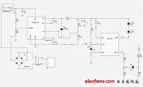
Figure 2 LED drive circuit diagram
SDEC 76-200KW Diesel Generator
Sdec 76-200Kw Diesel Generator,Sdec Standby Power Diesel Generator,Sdec Soundproof Type Diesel Generator,Sdec Canopy Type Diesel Generator
Shanghai Kosta Electric Co., Ltd. , https://www.shkostagenerator.com