The electrical schematic is a type of electrical system diagram. It is drawn according to the working principle of the control line diagram, and has a simple structure and a clear hierarchy. Mainly used to study and analyze the working principle of the circuit. All components in the electrical schematic diagram shall be in the form of graphic symbols and text symbols as specified in the national standard.
Component technical data needs to be marked in the electrical schematic
(1) Electrical component list: component name, symbol, function, model, quantity, etc.
(2) Note the graphic symbol in its electrical schematic with a small font.
Electrical principle icon note
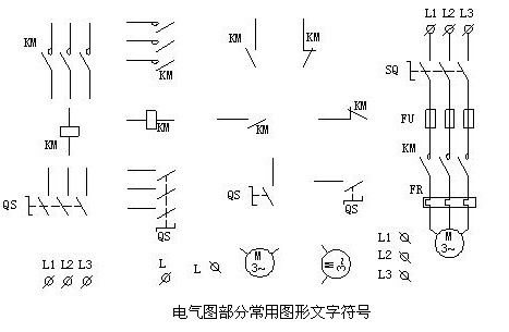
Common labels are: QS knife switch, FU fuse, KM contactor, KA intermediate relay, KT time relay, KS speed relay, FR thermal relay, SB button, SQ travel switch
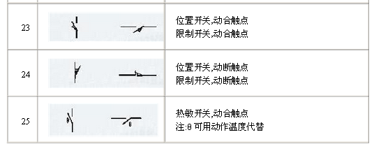
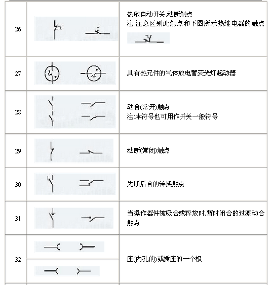
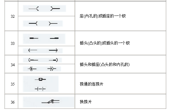
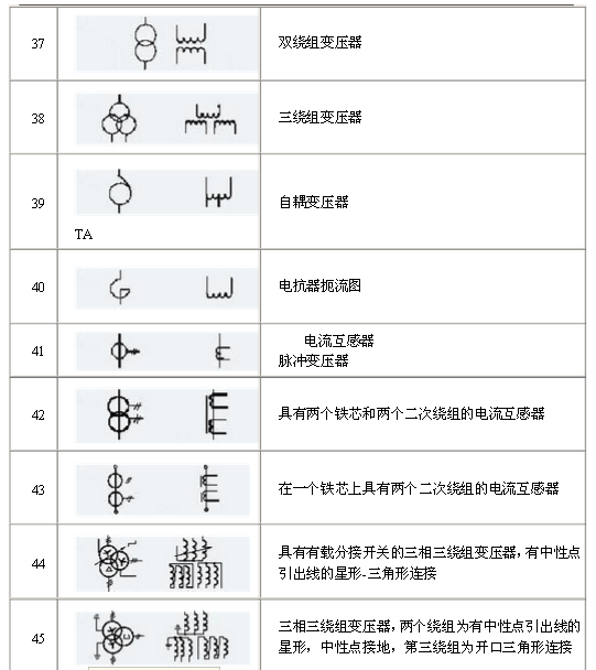
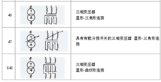
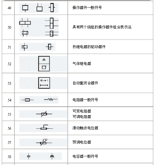
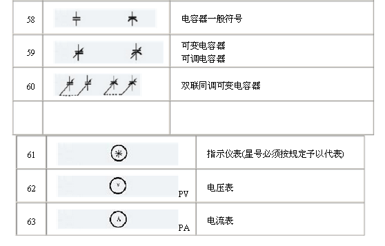
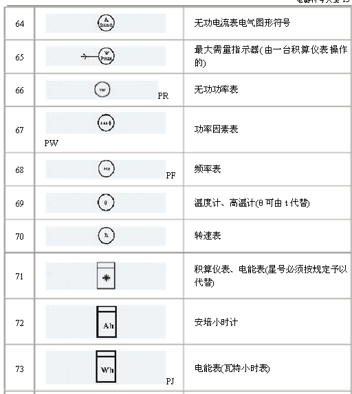
After the electrical drawing is commonly used for graphic size design, in the AutoCAD 2006 environment, the common graphic and text symbols of the electrical drawing are drawn, as shown in the figure.
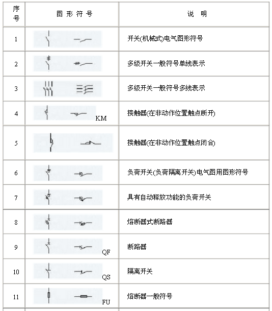
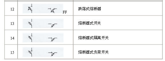
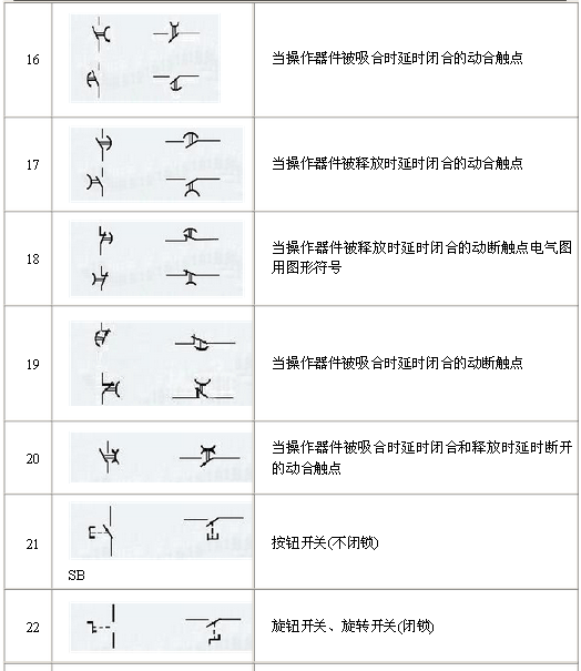
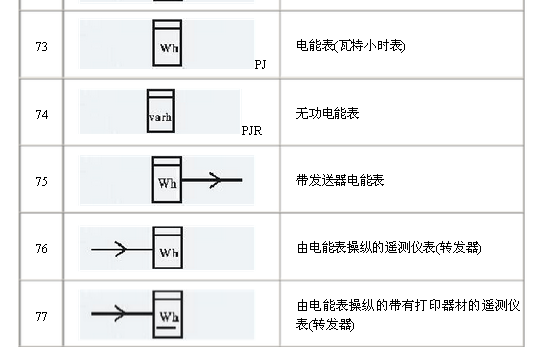
Detailed explanation of the electrical schematic symbols
power connector is used in power module system. It can select the matching power + signal connector according to the need. The feature is that the number of power and signal contacts and the matching sequence can be selected arbitrarily while keeping the connector size and contact core number unchanged.
Plug (male) / socket (female) can be installed at 90 or 180 degrees. It supports mixed or independent combination of signal and power. The quantity range of power and signal is (2-16) pin and (12-128) pin respectively
Product features
High temperature resistant, glass fiber reinforced and flame retardant polyester is used as insulation material
Copper gold composite conductor with high conductivity is used, and the contact area of the conductor is plated with gold
It adopts shrapnel contact, which has the characteristics of integration, small volume, large current carrying capacity, soft plug-in, blind plug-in, self guidance and high dynamic contact reliability. This series of products can be interchanged with FCI's powerblade series and Tyco's multi-beam series
There are three sizes of center distance of power contact: 5.08mm, 6.35mm and 7.62mm
The length of power hole / signal pin can be selected in two sizes. The power rated current is 45A and the signal rated current is 2.5A
Power+ Signal Power Connector
ShenZhen Antenk Electronics Co,Ltd , https://www.antenk.com