Although the tubes do not solve the problem of cost-performance and ratio of high-quality sound, they do have better input transmission characteristics than bipolar transistors, thus providing lower open-loop distortion.
The tube can also drive the difficult speaker load better than some solid-state devices, thereby more appropriately solving the load problem.
The power output tube has the ability to withstand large heat, so that it can work in the Class A state, which avoids the generation of high-order crossover distortion. However, these properties are mainly used in the transformer-coupled (this is necessary) output stage, not in the front. The advantages of using a tube in the pre-gain stage are few.
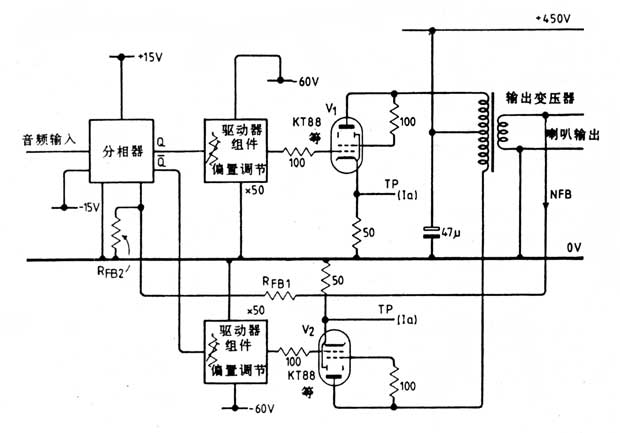
Figure 1 Structure of a single transistor / tube amplifier
The basic structure of the hybrid amplifier is shown in Figure 1. Figure 2 is the driver circuit. This circuit is a four-tube class-A amplifier circuit that I published in Wireless World in 1969. Because the driver circuit is directly coupled except for the DC blocking capacitor at the input, adjusting the input DC level of Tril will affect the DC output level, thereby controlling the gate bias of the output tube. Of course, if you use the push-pull method to drive two output tubes and use the output transformer secondary to realize the overall loop negative feedback, you need some kind of input phase splitter. Here, a phase splitter circuit is designed based on the wideband operational amplifier LM833 with little distortion, as shown in Figure 3. 
Figure 2 Transistor Class A drive circuit
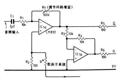
Figure 3 Two split-phase circuit schemes (a)

Figure 3 Two split-phase circuit schemes (b)
The frequency band of the circuit of Fig. 2 is in the range of 10MHz. If it is necessary to introduce a ladder in the gain / frequency curve to ensure the stability of the high-frequency loop of the final amplifier, just use an RX / CX network in parallel with R6, whose value mainly depends on the leakage reactance of the output transformer. The low-frequency cut-off point is determined by the values ​​of C1 and C3, and can be arbitrarily set according to the needs of low-frequency loop stability. The transient performance of the circuit in Fig. 2 is quite good. The distortion at the 1KHz point when the clipping has just occurred is on the order of 0.02%, which is almost entirely the second harmonic. Like the usual Class A gain stage, distortion will decrease linearly as the output voltage swing decreases.

Follow WeChat

Download Audiophile APP

Follow the audiophile class
related suggestion
'+ data.data.username +' '; dom + ='
We are the China leading Agents and suppliers of Medical Epidemic Preventive Materials, such as Medical Infrared Thermometer, forehead thermometer, Infrared forehead temperature detector, Infrared temperature tester,Infrared temperature instrument
We are specialized manufacturers from China, Infrared Thermometer, Medical Materials suppliers/factory, wholesale high-quality products of medical Epidemic Preventive materials R & D and manufacturing, we have the perfect after-sales service and technical support. Look forward to your cooperation!
Medical Infrared Thermometer
Medical Infrared Thermometer, forehead thermometer, Infrared forehead temperature detector, Infrared temperature tester Infrared temperature instrument
Shenzhen Daceen Technology Co., Ltd. , https://www.daceen-sz.com