Abstract: This paper studies and analyzes the shortcomings of existing car anti-theft systems. This paper presents a design scheme of car anti-theft system based on car networking and GSM network. The realization idea of ​​the scheme is that the main controller obtains the state of the vehicle in real time through the vehicle network and monitors it. When the theft occurs, the vehicle state information and the current location information are transmitted to the owner's mobile phone in real time through the GSM network, and at the same time, The vehicle owner can cut off the fuel supply by remote command, thereby realizing the function of car theft prevention.
This article refers to the address: http://
0 Preface
The existing car anti-theft system mainly has active and passive types. The active type is represented by GPS (Global Position System) anti-theft system. Although the anti-theft system can monitor and track the vehicle status in real time, the owner often needs to pay the service provider every year. The cost, passive anti-theft system is represented by PATS (Passive Anti Theft System), which can effectively prevent the car from starting the engine under illegal conditions, but once the system is cracked or the vehicle is forcibly moved, the owner can do nothing. Therefore, it is especially important to design a two-way car alarm system with low price and high real-time performance.
1 anti-theft system structure design
The structure of the car anti-theft system based on the GSM (Global System for Mobile Communications) module is shown in Figure 1. The system consists of a main controller, an acceleration module, a GPS module, an in-vehicle network interface, a GSM module, and a power module.
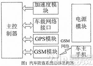
The anti-theft system is connected to the car on-board CAN network through the CAN (Controller Area Network) interface, and communication with other in-vehicle networks is realized through the gateway. By monitoring the car anti-theft state and the door switch in real time, the acceleration module in the anti-theft system monitors the body condition. When a thief tries to move the vehicle through an illegal way, the main controller module reads the GPS module to obtain the current position of the vehicle, and then sends information to the owner's mobile phone through the GSM module, and the owner can issue a command to the anti-theft system to cut off the car through the mobile phone. The supply of fuel to achieve the purpose of theft prevention.
2 anti-theft system hardware design
The anti-theft system that realizes the above structure mainly designs a main controller, a GSM module, a CAN interface, a GPS module, an acceleration module, and the like.
2.1 main controller
The main controller is the core of the whole anti-theft system. This paper selects the STM32F103 series MCU with stable performance and powerful function as the main controller. The main controller and peripheral circuit are shown in Figure 2.
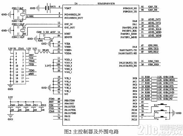
The main controller and peripheral circuits are mainly composed of main clock, reset, and JTAG (Joint Test Action Group) downloading. The main controller has an RTC (Real Time Clock) function, and the circuit clock signal relies on an external 32.7 68K crystal oscillator. When the system is powered off, it is powered by the backup battery.
2. 2 GSM module
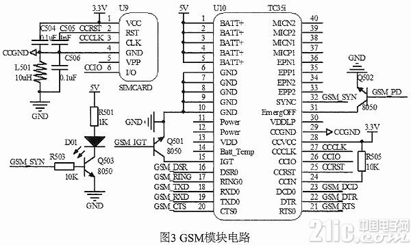
The GSM module circuit is shown in Figure 3. This circuit uses Siemens' dual-frequency industrial-grade GSM module TC35i. This circuit sends messages to the owner's mobile phone under the control of the main controller, and receives the relevant control commands of the owner.
2.3 GSP module
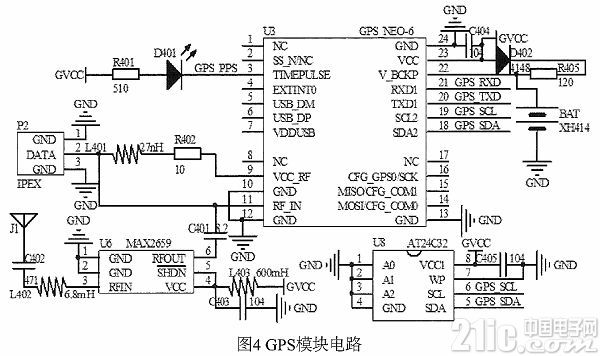
The GPS module circuit is shown in Figure 4. The circuit uses the U-Blox GPS chip NEO-6M as the core, and realizes the GPS positioning function under the control of the main controller. The GPS chip and the main controller pass through the serial bus. In the communication, the EE PROM (Electrically Erasable Programmable Read-Only Memory) chip AT24C32 is used to save the relevant setting parameters of the GPS.
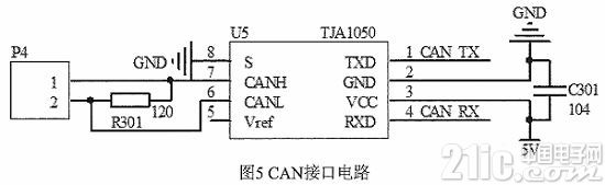
2.4 CAN interface
CAN interface circuit shown in Figure 5, STM32F103 series MCU comes with CAN network interface, therefore, only need to add a bus driver between the main controller and the car CAN network, this article selects TJA1050 with differential transmission and differential receiving function . The circuit connects the main controller to the vehicle network, and the main controller can obtain the state of the car such as the car door switch and the lock information through the vehicle network, and can also issue a command to the body control module in an emergency to cut off the power supply of the fuel pump.
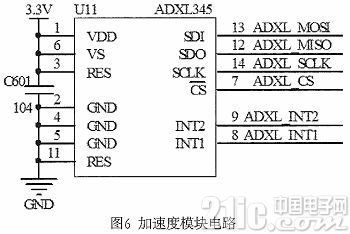
2.5 Acceleration Module
Acceleration module circuit shown in Figure 6, ADXL345 is a digital three-axis accelerometer produced by Analog Devices of the United States, featuring small and light, ultra-low power consumption, variable range, high resolution, etc. Its output uses I2C and SPI bus. The circuit is used for detecting the posture and movement state of the vehicle body. After the vehicle owner locks the vehicle through the remote controller, the main control reads the current body posture information of the automobile as an initial value. When the vehicle body vibrates, tilts, and moves, the output value of the three axes is The initial values ​​are compared, and when the difference between the two exceeds the set value, it is determined to be illegal.
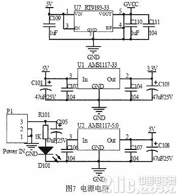
2.6 Power Module
The circuit circuit is shown in Figure 7. The 12V supply voltage is supplied from the car battery and converted to the required voltage by a three-terminal regulator.
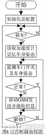
3 anti-theft system software design
The control process of the main controller is shown in Figure 8. The overall idea of ​​the software design is that after power-on, the main controller initializes its own parameters and each module, and reads the state of the car's own anti-theft system through the CAN interface. When the car is in the lock When the vehicle is in the state, the body posture information is read and memorized, and the door switch and the vehicle body posture are monitored. When an abnormality occurs, the GSM module is started to send the vehicle state and the GPS position information to the owner's mobile phone, and the vehicle owner is informed to take measures in time.
In addition to the above modules and circuits, the car anti-theft system studied in this paper should also include a PC software for the mobile phone. The PC software is responsible for receiving the car status information and GPS positioning information sent by the main controller of the anti-theft system via the GSM network. Will not be introduced.
4 test results
The car anti-theft system opens the door in the car to simulate the theft environment, and can successfully obtain the GSP positioning information in the host computer. The pre-set mobile phone receives the car status information, and its GPS positioning information and short message are shown in FIG. 9 and FIG. Show.
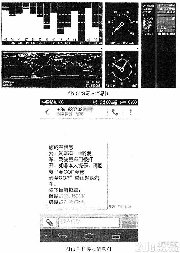
Through testing, the anti-theft system can effectively realize the state of the car and the attitude monitoring of the vehicle body, and can successfully send the car state and GPS positioning information to the owner's mobile phone when the theft occurs.
5 Conclusion
This paper proposes a car anti-theft system based on GSM module, which enables the owner to understand the status and position of the car in real time, to ensure the safety of the car is safe, the owner only needs to buy a mobile phone card, the cost is very low, and has a high market application and promotion. value.
Alarm Accessories,Alarm Products,Alarm Equipment
Chinasky Electronics Co., Ltd. , https://www.chinaskyswitches.com