A three-terminal Zener diode is a semiconductor device that has a very high resistance until a critical reverse breakdown voltage. When the voltage regulator is in reverse breakdown, it is almost constant in a certain current range (or within a certain power loss range), and the terminal voltage is almost constant, which shows the voltage regulation characteristics, and thus is widely used in a regulated Power Supply and a limiting circuit. Among them.
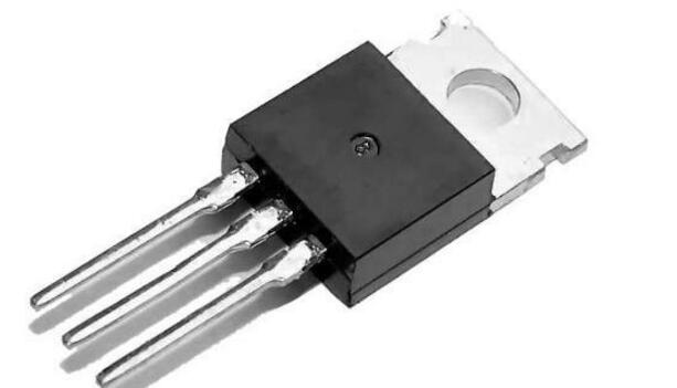
There are two kinds of three-terminal voltage regulator tubes. One type of output voltage is fixed, which is called fixed output three-terminal voltage regulator tube. The other output voltage is adjustable, which is called adjustable output three-terminal regulator tube.
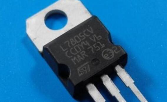
Because the fixed three-terminal regulator is a series regulator circuit, its principle is equivalent to the series regulator circuit.
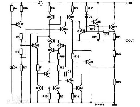
The voltage divider composed of R1, Rp and R2 is a sampling circuit, and a part of the voltage UB2 is taken out from the output terminal as a sampling voltage and applied to the base of the transistor T2. The Zener diode Dz is applied to the emitter of T2 with its stable voltage Uz as a reference voltage. R3 is the current limiting resistor of the Zener diode. The transistor T2 constitutes a comparison amplifying circuit which compares and amplifies the sampling voltage UB2 with the reference voltage Uz, and then controls the base potential of the transistor T1. The input voltage Ui is applied to the circuit in which the transistor T1 is connected in series with the load RL. Therefore, by changing the voltage drop UCE1 between the T1 collectors, the voltage Uo across the RL can be adjusted. That is to say, the output voltage Uo of the voltage stabilizing circuit can be adjusted by the transistor T1, so T1 is called an adjusting tube. Since the adjustment element is a transistor tube and is connected in series with the load in the circuit, it is called a transistor series regulator circuit. The base bias resistors of resistors R4 and T1 are also the collector load resistors of T2.
When the grid voltage is reduced or the load resistance is decreased and the output voltage is decreased, the sampling voltage UB2 is correspondingly decreased, and the T2 base potential is decreased. However, due to the T2 emitter potential, the stable Uz of the Zener tube remains unchanged, so the emitter voltage UBE2 is reduced, resulting in a decrease in the collector current of T2 and an increase in the collector potential Uc2. Since the collector of the amplifying tube T2 is connected to the base of the adjusting tube T1, the base potential of the T1 rises, causing the collector current to increase and the tube pressure drop UCE1 to decrease. Since T1 is connected in series with RL, the output voltage Uo is substantially unchanged.
Similarly, when the output voltage Uo increases due to changes in the grid voltage or load, the tube pressure drop UCE1 of the adjustment and adjustment tube is increased by sampling, comparison, amplification, adjustment, etc., and as a result, the voltage at the output terminal is suppressed from increasing. The output voltage remains essentially the same.
Adjust the potentiometer Rp to fine tune the output voltage. The adjustment tube T1 and the load resistor RL are composed of an emitter output circuit, so they have a stable output voltage.
During the operation of the series-type regulated power supply circuit, the adjustment tube is always in an amplified state. By adjusting the current of the tube to be equal to the load current, it is necessary to select an appropriate high-power tube as the adjustment tube and install the heat sink as specified. In order to prevent short circuit or long-term overload and burn out the regulating tube, circuits such as short circuit protection and overload protection are generally provided in the DC voltage regulator.
Diy Game Kit,Arcade Joystick Diy,Diy Game Console Kit,Diy Handheld Game Console Kit
Guangzhou Ruihong Electronic Technology CO.,Ltd , https://www.callegame.com