In the past, when we checked the quality of the 50-week power frequency transformer, we generally checked the excitation current or the leakage current flowing through the primary coil of the switching transformer under the highest input voltage for the 50-week power frequency transformer. However, many people are currently only checking the inductance or leakage inductance of the switching transformer when checking the quality of the switching transformer. Now, can we check the excitation current of the switching transformer just like the 50-week power frequency transformer? - It's hard. Because the switching transformers are generally operated in a unipolar magnetization state, the excitation current of the test switching transformer requires a high-power DC pulse output power supply. This high-power DC pulse output power supply is unsafe to operate and inconvenient to operate.
To this end, we can use another simpler method, the current superposition method, to test the volt-second capacity of the switching transformer. The current superposition method is to superimpose the current in the switching transformer coil, magnetize the switching transformer core, and then measure the inductance of the switching transformer, thereby indirectly measuring the limit volt-second capacity VTmax and the maximum volt-second of the switching transformer coil. Capacity VTm.
The limit volt-second capacity VTmax here refers to the corresponding VT value when the switching transformer core reaches saturation; and the maximum volt-second capacity VTm indicates the maximum value that the volt-second capacity VT of the switching transformer should not exceed in practical applications.
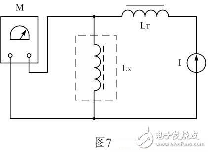
Figure 7 is a schematic diagram of the operation of testing the inductance or volt-second capacity of a switching transformer using current superposition. In Figure 7, M is the inductance tester, LT is the isolated inductor, I is the current source, and Lx is the primary inductance of the switching transformer to be tested. The inductance of the LT must be much larger than the inductance of the primary winding of the switched transformer. If the current source I is an ideal constant current source, the isolation inductor LT can be omitted. Let us introduce the working principle of Figure 7.
Generally, when measuring the inductance, the inductor is passed through a 1KHz or 10KHz AC, and then the impedance (inductance) of the inductor is indirectly measured by testing the current flowing through the inductor. Since the current flowing through the inductor is small and is an alternating current, the inductance measured by this method is different from the inductance exhibited by the inductor when operating, and the difference is large because the core of the switching transformer The magnetic permeability is not a constant.
If the tested inductor flows through a variable current, the operating point of the magnetizing curve of the tested inductor can be changed. Thus, the permeability or inductance of any point on the magnetization curve can be tested and can be varied according to the inductance. Find the operating point at the time of magnetic saturation, and further measure or calculate the limit volt-second capacity VTmax of the switching transformer according to the magnetic saturation operating point. Knowing the limit volt-second capacity VTmax of the switching transformer, the maximum volt-second capacity VTm of the switching transformer can be determined according to the actual application of the user.
Let us analyze how to define the magnitude of the superimposed current and the test of the volt-second capacity VT of the switching transformer.
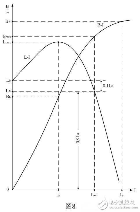
Figure 8 is a graph showing the current-inductance or current-magnetic induction intensity function of the switch transformer core with air gap. In Figure 8, the X-axis represents the superimposed current I flowing through the switching transformer coil, and the Y-axis represents the switching transformer coil. Inductance L or magnetic induction intensity B in the core of the switching transformer; LI is the curve of the switching transformer inductance L corresponding to the superimposed current I, and BI is the variation curve of the magnetic induction B of the switching transformer core corresponding to the superimposed current I ( Initial magnetization curve).
When the superimposed current I = 0, the inductance of the switching transformer coil is measured as L0. Since the magnetic permeability of the switching transformer core is relatively small, the initial inductance L0 of the switching transformer coil is relatively small; When the superimposed current I increases, the magnetic permeability of the switching transformer core also increases, so the inductance of the switching transformer coil also increases with the increase of the superimposed current I, when the superimposed current I reaches a certain value (I = Ib) When the inductance of the switching transformer coil reaches the maximum value Lmax; then, as the superimposed current I increases, the inductance of the switching transformer coil decreases and rapidly decreases. When the superimposed current I = Is, the switch The magnetic induction of the transformer core begins to saturate (B = Bs), and the inductance of the switching transformer coil is reduced to almost equal to zero.
In fact, the magnitude of the superimposed current I in Figure 8 is equivalent to the sawtooth current in Figure 2-b), i.e., the inductance of the switching transformer coil is modulated by the DC component flowing through the coil of the switching transformer. If we correspond the maximum current Im flowing through the switching transformer coil to the maximum magnetic induction intensity Bm of the switching transformer core, then we can use Figure 8 to define the maximum current Im flowing through the switching transformer coil and the maximum magnetic induction of the switching transformer core. Strength Bm.
Since the concept of maximum magnetic induction Bm is often used, in order to avoid confusion, we hereby define two new concepts: one for the ultimate magnetic induction Bmax and the other for the limiting current Imax.
Correspondingly, we also define: When the current I flowing through the primary winding of the switching transformer causes the inductance L of the primary winding of the switching transformer to drop to 90% of the initial inductance L0, the current of the current-switching transformer coil is called For the limit current Imax, which corresponds to the magnetic induction B in the core of the switching transformer, we call it the limit magnetic induction Bmax.
Any one of the inductors with a core can be measured by the measurement method shown in Fig. 7 to measure the initial inductance L0 and the maximum inductance Lm of the inductor, and the limit current Imax. By measuring the inductance and its corresponding limit current value Imax, the limit volt-second capacity VTmax of the switching transformer or the energy storage inductor can be calculated. During the use of the switching transformer, the limit volt-second capacity VTmax of the switching transformer must not be exceeded at any time.
Conversely, we can also define (or measure) the duty cycle of the switching power supply or the pulse width of the output voltage under certain conditions, such as the highest operating voltage and the heaviest load, and then calculate the switching transformer. The maximum value of the primary coil current is Im, and finally the maximum value Im is multiplied by a safety factor K (K = 1.43). The result is the limit value Imax flowing through the primary winding current of the switching transformer, which is used to measure the primary winding inductance Lx of the switching transformer. The superimposed current value.
It can be seen that the switching transformer (flyback type) in any case, the operating current of the primary coil can not exceed Imax in Figure 8, the corresponding magnetic induction can not exceed Bmax in Figure 8.
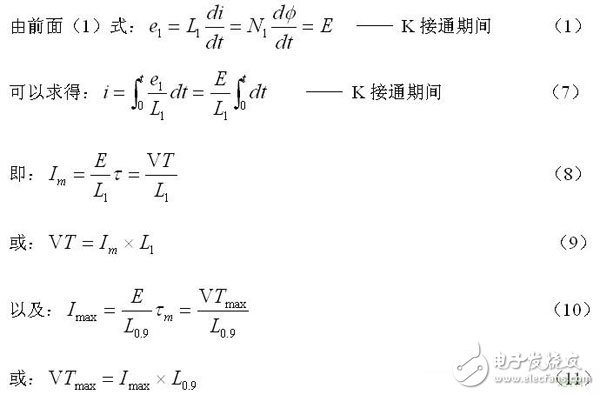
The above formula (8) is used to calculate the current of the primary transformer or the storage inductor coil of the switching transformer, where is the maximum value of the current of the primary winding or the energy storage inductor of the flow switching transformer, that is, when the switch K in Fig. 1 is connected After passing, its duration is equal to the instantaneous value of the current flowing through the primary winding of the switching transformer or the energy storage inductor; E is the operating voltage of the switching power supply, and V is the input voltage (DC pulse voltage) applied across the primary winding of the switching transformer. L1 is the inductance of the primary coil of the switching transformer.
Equation (9) is a formula for calculating the volt-second capacity VT of a switching transformer or an energy storage inductor, and corresponds to equations (8) and (10) and (11).
Equation (10) is a formula used to calculate the ultimate volt-second capacity VTmax of a switching transformer or an energy storage inductor. Where: VTmax switching transformer or inductor or energy storage inductor coil limit volt-second capacity, V is the amplitude of the DC pulse applied to the primary coil of the switching transformer (unit: volts), Tmax is added to the switching transformer primary coil or stored The limit time (width, in seconds) of the DC pulse at both ends of the inductor coil;
Imax is the limit superimposed current when testing the primary winding of the switching transformer or the inductance Lx of the storage inductor according to Figure 7, that is, when the superimposed current I is increased, the measuring inductance Lx of the primary winding or the storage inductor of the switching transformer is equal to The value of the superimposed current flowing through the primary winding of the switching transformer or the energy storage inductor when the initial inductance is 0.9 times. Imax can also be regarded as the limit current flowing through the primary or storage inductor of the switching transformer. This current can be measured by the method defined in Figure 7 and Figure 8; the initial inductance of the primary or energy storage inductor of the switching transformer. The value when it drops to 90%.
By the way, Imax, VTm and VTmax are basically the same in nature, except that the latter uses max to indicate that it is the limit value of the former.
Fork Type Terminals,Insulated Bullet Sockets Terminals,Insulated Bullet Terminals,Type Fork Insulate Terminal
Taixing Longyi Terminals Co.,Ltd. , https://www.lycopperterminals.com