Using op amp feedback and reference voltage to generate dc current of any size is a simple and straightforward process. However, suppose that you need to generate some arbitrary number (in N for example) current sink/source, and each current sink/source is arbitrary, and may need to be biased for some complex analog circuits in different stages. . Although the generation of the reference voltage only needs to be performed once, the repetition of the entire feedback portion of the current sink makes the cost and design space intensive. So the question is: Can a single feedback source be used to implement this bias network? The answer is yes, although it is somewhat complicated, certain conditions must be met. The network (in this analysis, only the current sink is taken as an example) is shown in Figure 1.
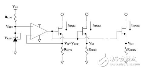
Figure 1: Current sinking network
The final MOSFET (Gold Oxygen Half Field Effect Transistor) source voltage VS and RSET resistance determine the sink current on each column; by removing the feedback from the external current sink column (ie, all N"1), the VSN has been lost. Direct control. Therefore, RSETN must be carefully chosen to generate the sink current for any Nth column expected, ie ISINKN. Looking closely at Figure 1 above, it is easy to derive an equation that defines the ratio of the Nth column current to the first column current of the bias network:
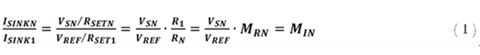
Re-adjust Equation 1 to obtain the R1 to RN resistance ratio MRN, and the equation becomes:
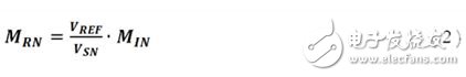
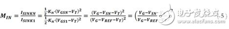
So what is the MOSFET source voltage of the Nth column of the bias network, VSN? Considering that the NMOS drain current equation operating in the saturation region is:
![]()
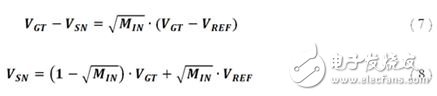
It must be noted that the effect of channel width modulation can be largely ignored here. This is because any rise in drain current due to rising drain voltage will drop after passing through the RSET resistor and cause the source voltage to rise. In order for the MOSFET to sustain any current, the gate voltage must be greater than the sum of the source voltage and the threshold voltage. That is, given a gate voltage, the source voltage will be limited to a value that is at least one threshold voltage less than the gate voltage, and a larger drain voltage rise will not raise the drain current. Therefore, to build the appropriate operating conditions, RSET must be large enough to ensure that the following assumptions are allowed under the above restrictions:
![]()
The ratio in Equation 1 can be rewritten based on Equations 3 and 4 as:
To simplify Equation 5, the following definitions can be made:
After replacing and adjusting with Equation 5, the VSN equation can be derived:
Substituting Equation 8 into Equation 2 yields:
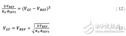
So what is the difference between the gate drive and the threshold voltage, VGT? This is ultimately determined by the feedback of the first column of the bias network; it is essentially the voltage required to maintain the desired ISINK1 current:
![]()
Re-adjust the terms of Equation 11 to derive the equation for VGT:
Substituting Equation 13 into Equation 10 yields:
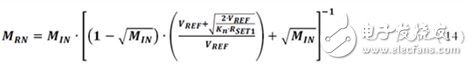
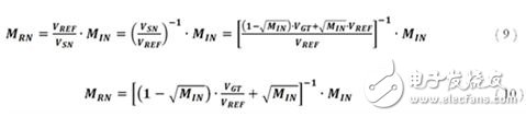
Finally, the resistance ratio MRN can simply be written as a function of MIN (plus some physical constants of the bias network device) as follows:
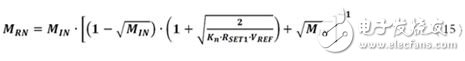
Now that the equation for the RSET resistance ratio has been derived, the implications and implications of establishing a bias current network of any size can be explored.
USB 2.0 is a USB interface standard released in 2000 with a theoretical maximum transmission speed of 480Mbps (about 60MB/s). The port has four cables (five cables for MicroUSB and MiniUSB), and the maximum output current is 0.5A. USB 2.0 is currently the most common version of USB port, almost all computers have USB 2.0 port, most USB devices also support USB 2.0. USB 2.0 hub. The device can provide USB high speed or full speed connection on the uplink port. The device also provides USB high-speed, full-speed, or low-speed connections on the downlink port. When the uplink port is connected to an electrical environment that supports only high-speed, full-speed, and low-speed connections, the high-speed, full-speed, and low-speed USB connections on the downlink port are enabled. When the uplink port is connected to an electrical environment that supports only full or low speed connections, the USB high-speed connection on the downlink port is disabled. USB 3.0 Hubs is higher than usb 2.0 in terms of transmitting data.

Usb 2.0 Hubs,7 Port Usb 2.0 Hub,Wireless Usb 2.0 Hub,Usb C To Usb 2.0 Hub
Henan Yijiao Trading Co., Ltd , https://www.yjusbhubs.com