Abstract: This paper introduces an FPGA-based smart car design. The system uses the PWM wave generated by FPGA to control the speed of the car. The infrared sensor TCRT5000 detects the black track on the road. The well feeds the detected signal back to the control chip FPCA. The collected signals issue commands to control the motor drive circuit of the trolley to adjust the driving direction, so that the trolley can automatically travel along the black trajectory, and the ultrasonic module is used to detect the obstacles in front of the vehicle in real time, thereby realizing the obstacle avoidance function of the trolley. .
This article refers to the address: http://
As FPGAs are upgraded from programmable logic chips to programmable system-on-chips, their role in circuits has expanded from the initial logic glue to digital signal processing, interfaces, high-density computing, etc., and applications have also extended from communications. To consumer electronics, automotive electronics, industrial control, medical electronics and more. Based on the research of embedded operating system, this paper proposes a smart car design scheme based on FPGA, which is designed to automatically monitor and control the special environment such as work site and dangerous working area. It is controlled by Altera's CycloneIIEP2 C5T chip. At the same time, the infrared sensor and ultrasonic sensor are used at the same time, and a smart car system with obstacle avoidance tracking function is designed.
1 system plan
This design is to realize a smart car control system that can automatically avoid obstacles by automatic tracking. The FPCA chip is used to realize the functions of intelligent car control, etc. The common motor model car is selected as the mechanical platform, and the sensor design is combined with the sensor technology. Knowledge of motor control technology to achieve the various functions of the car. The design is completed by a hardware module consisting of infrared automatic tracing and ultrasonic automatic obstacle avoidance combined with software design to form a multi-functional smart car, which can realize the forward and backward movement of the car, and automatically navigate according to the ground black line tracing and detect obstacles. Barriers and real-time display of obstacle distance and other functions to achieve intelligent control.
2 overall design
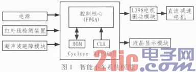
The smart car is composed of a sensor signal processing module, a motor drive module and a control module, and cooperates with the sensing system and the motor drive circuit of the vehicle to realize the function of the autonomous movement of the trolley, wherein each system module is described in the VHDL language and is in the FPGA chip. Realize automatic tracking and obstacle avoidance, and display obstacle distance and other functions on the LED screen. The working principle of the logic circuit is based on the data sent back by the infrared sensor. The system uses four infrared radiation sensors to detect the sensor signals through the FPGA to realize the obstacle avoidance of the vehicle. The principle of ultrasonic ranging generally adopts the TOF method of the transit time method. Firstly, the time elapsed from the launch of the ultrasonic wave to the return of the obstacle is measured, and then the speed of the ultrasonic wave is doubled to obtain the distance between the sound source and the obstacle. . Control the running state of the car model, such as forward, reverse, left turn, right turn, the server side turns on the GPIO driver, outputs the control signal through the CPIO port, controls the FPCA output duty cycle adjustable PWM signal, and can control the running state of the car model. The motor control uses PWM pulse width modulation to control the forward speed of the car. The PWM signal is fed to the control terminal of the motor drive chip to adjust the speed. The block diagram of the car system is shown in Figure 1.
3 system hardware design
3.1 Photoelectric detection circuit
The TCRT5000 photoelectric sensor module is an infrared reflective photoelectric switch based on the TCRT5000 infrared photoelectric sensor. The sensor is composed of a high-power infrared photodiode and a high-sensitivity phototransistor. The output signal is shaped by a Schmitt circuit and is stable and reliable. The infrared emitting diode of the sensor continuously emits infrared rays. When the emitted infrared rays are not reflected back or reflected back but the intensity is not enough, the phototransistor is always in the off state. At this time, the output end of the module is low, indicating the diode When the detected object appears in the detection range, the infrared light is reflected back and the intensity is large enough, and the photodiode is saturated. At this time, the output end of the module is high, indicating that the diode is illuminated. TCRT5000 reflective photoelectric sensor is a commonly used sensor. This series of sensors is complete in variety, low in price, small in size, easy to use, reliable in quality and widely used. The sensor consists of a reflective module (light emitting diode) and a receiving module (photosensitive transistor). By transmitting the infrared signal, the change of the received signal is judged to detect the change of the state of the detected object. FIG. 2 is a circuit schematic diagram and a physical map of the TCRT5000 sensor module.
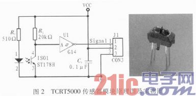
When the car is driving on the white ground, the infrared transmitting tube installed under the car emits an infrared signal, which is reflected by the white, and is received by the receiving tube. Once the receiving tube receives the signal, the phototransistor in the figure will be turned on, and the comparator output is Low level; when the car travels to the black guide line, the infrared signal is absorbed by black, the phototransistor is turned off, and the comparator outputs high electrons, thereby realizing the function of detecting signals by infrared rays. Sending the detected signal to the I/O port of the control module. When the signal detected by the I/O port is high, it indicates that the infrared light is absorbed by the black guide line on the ground, indicating that the car is on the black guide line. Similarly, when the signal detected by the I/O port is low, it indicates that the car is driving on the white ground.
The hysteresis comparator LM324 acts as an anti-interference function in the system. The LM324 is a quad op amp integrated circuit packaged in a 14-pin dual in-line plastic package. There are four operational amplifiers inside and a phase compensation circuit. The circuit consumes a small amount of power and has a wide operating voltage range. It can be operated with a positive power supply of 3 to 30 V, or a positive and negative dual power supply of ±1.5 to ±15 V. In the black line detection circuit, it is used to determine the level of the electrons of the infrared receiving signal, and the level of the black line is determined by the level. In the circuit, one input of the LM324 needs to be connected with a sliding rheostat. By changing the resistance of the sliding rheostat to provide a suitable comparison voltage, Figure 3 is the pin diagram of the LM324.
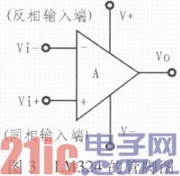
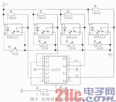
Figure 4 is an infrared pair tube black line detection circuit.
3.2 Ultrasonic sensing module
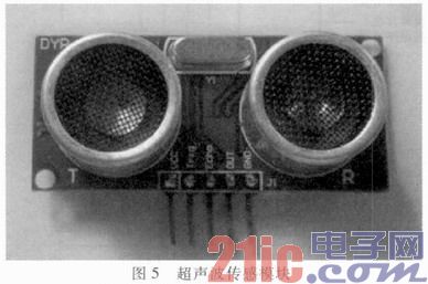
The principle of ultrasonic generator ranging is to emit an ultrasonic signal with a length of about 6 mm and a frequency of 40 kHz through the transmitter. This signal is reflected by the object and accepted by the receiving head. The receiving head is essentially a piezoelectric effect transducer. . It receives a signal and produces a weak voltage signal of the mv level. The ultrasonic sensing module is shown in Figure 5.
Ultrasonic ranging is achieved by means of an ultrasonic pulse echo transit time method. The principle block diagram is shown in Figure 6.
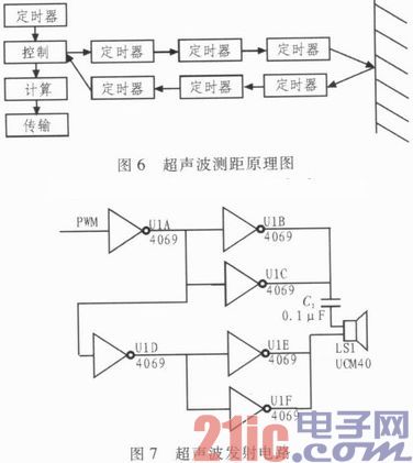
The ultrasonic transmitting circuit is shown in Figure 7.
3.3 Motor drive circuit
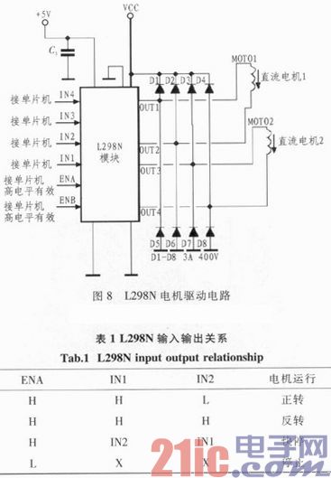
The motor drive module uses the special chip L298N as the motor drive chip. The L298N is a full-bridge driver chip with high voltage and large current. Its response frequency is high, and one L298N can control two DC motors separately. Table 1 shows the L298N function table. The 5, 7, 10, and 12 pins of L298N are connected to the FPGA. The PWM speed control of the two DC motors can be realized by programming the FPGA. The design of the drive circuit is shown in Figure 8.
4 system software design
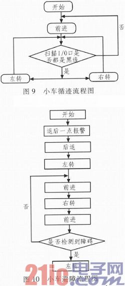
The system uses PWM to adjust the speed of the DC motor, and realizes the logic gate control of the FPGA through VHDL language programming. After the car enters the tracking mode, it starts to scan the single-chip I/O port connected to the infrared detector. Once it detects a signal change of an I/O port, it executes the corresponding judgment program and sends the corresponding signal. Give the motor to correct the running state of the car. The flow chart of the car tracking obstacle avoidance is shown in Figure 9 and Figure 10, respectively.
5 system test
In order to test the normal operation of the smart car system, the design scene was tested on the tracking car system. The test route is laid with black electrical tape and laid on a light-colored floor. The track is S-shaped. At the starting point and at the end of each destination, there is a black horizontal line running through the track to indicate the parking spot. After the S-type track is over, the obstacles on the ground are placed arbitrarily, and the obstacles are taken to the designated place to stop.
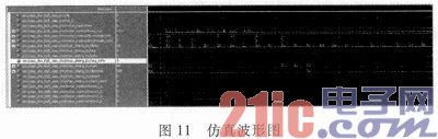
The simulation waveforms obtained on the Quartus II software are shown in Figure 11 through software and hardware debugging.
6 Conclusion
The smart car designed in this paper uses the infrared sensor TRTC5000 as the tracking module and FPCA as the main control chip. The modular design of the car uses the modular design, which makes the system simple, fast response, stable performance, and the obstacle-proof function is realized by the test car.
Small Servo Drives,Motor Servo Drives,Ac Drive Frequency Converter,Variable Frequency Drive Electric Motor
Zhejiang Synmot Electrical Technology Co., Ltd , https://www.synmot-electrical.com