Abstract: The guided filtering algorithm is widely used in the field of image processing. It has a good processing effect in terms of rain, snow, defogging, foreground extraction, image denoising, image enhancement, cascade sampling and so on. But for real-time applications, software implementations are difficult to meet. It is proposed to use the software and hardware collaborative development strategy to achieve boot filter hardware acceleration in SDSoC environment. The boot filter algorithm is implemented by debugging the C language code in the SDSoC development environment, and the functions affecting the performance are implemented by the Zedboard development version hardware developed by Xilinx. In the design, the stream data method, PS (Processing System) and PL (Programmable Logic) side collaborative development strategy, and software and hardware parallel, pipeline optimization and other optimization methods are adopted to improve the overall performance of the accelerator. The experimental results show that the proposed software and hardware cooperative guided filter accelerator has an acceleration ratio of up to 16.
0 PrefaceIn 2010, HE KM et al. proposed the Guided Filter [1] algorithm. The biggest similarity between this algorithm and bilateral filtering is that it also has the edge-maintaining feature, except that it also overcomes the effect of artifact removal. This algorithm is widely used in the field of image processing, and has good processing effects in terms of rain and snow [2], defogging [3], foreground extraction [4], image denoising, image enhancement, cascade sampling and so on.
However, as the size of the processed image continues to expand, the boot-filtering algorithm based on CPU processing is increasingly unable to meet people's needs. Therefore, Wang Xinlei et al. [5] implemented GPU-based GPU-accelerated GPU acceleration. In order to enable the boot filter to achieve real-time processing in the embedded field, this paper proposes a method based on FPGA to accelerate the boot filter.
The basis of the guided filtering theory is the local linear model. The model considers that any point on an arbitrary function and a point adjacent to the point can be regarded as a linear relationship, and a complex function can be represented by many local linear functions. If you need to find the value of a point on the function, you only need to find the value of all linear functions containing the point, and find the average of the values ​​of these linear functions, which is the value of the point on the function.
2 Guided Filter Accelerator Design2.1 Introduction to the experimental environment
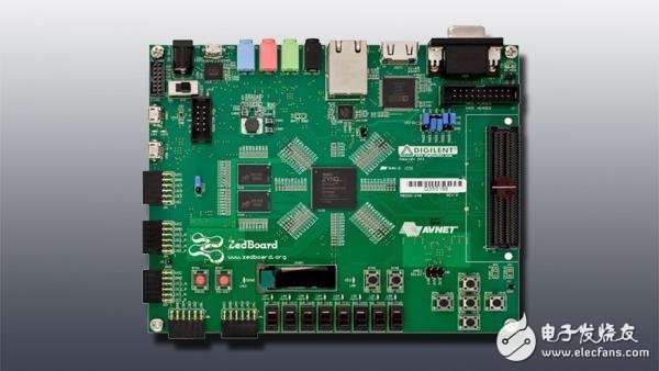
This article uses Zynq-7000 series Zedboard development board [6] as a hardware development environment, and its PS side provides ARM Cortex-A9 processor, 512 MB DDR3 memory space and external storage interface. Its PL-side XC7Z020 CLG481-1 EEP chip provides a programmable logic array unit that provides a rich logic resource for hardware acceleration. This article uses SDSoC [7] as a software development environment, which is an IDE (Integrated Development Environment) based on Zynq-7000 fully programmable chip in embedded systems.
2.2 Algorithm structure design
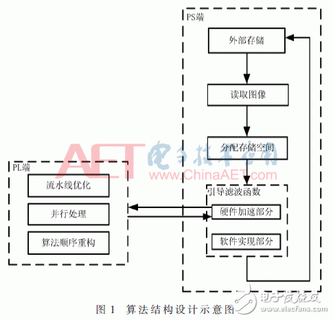
In this paper, the image data of a single channel is stored in the external storage of the PS side, and then the data is read into the memory. In order to obtain the maximum computing performance, the image buffer space required by the algorithm is allocated before the boot filter function is called, and the memory space pointer is passed as a parameter to the boot filter function for use, and then the PS end calls the boot filter function. In this paper, the guided filtering algorithm is divided into two parts, one of which is to accelerate the function which has a great influence on the algorithm by hardware, the hardware acceleration part to transmit the data to the PL end, and the PL end to realize it by the hardware logic circuit. The algorithm is optimized by optimization methods such as pipeline, parallel processing and algorithm reconstruction. After processing the data, write the data back to the PS side. Finally, the PS side stores the processed image in external storage. The algorithm structure design is shown in Figure 1.
2.3 Optimization method
2.3.1 Stream Data Transmission
In order to obtain the maximum transmission performance of the PS and PL ends, this paper uses the sds_alloc function [8] in the SDSoC development environment to apply for a continuous physical address as an image buffer on the PS side, and inserts the parameter #pragma that guides the compiler before the hardware function declaration. The SDS dada zero_copy(imgIn[0:rows*cols]) and #pragma SDS data access_pattern(imgIn[0:rows*cols]) commands convert image data into stream data [8] for transmission.
2.3.2 Pipeline Optimization
In order to increase the concurrency of the program, the pipeline optimization can start the next operation before the current operation is completed. Environment SDSoC's PIPELINE[8,10] optimization instructions optimize functions and loops. The following is a description of the pipeline of the function and the optimization of the pipeline of the loop.
(1) Pipeline operation of functions
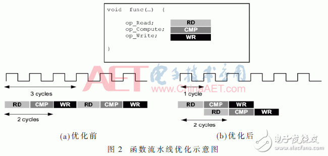
As can be seen from Figure 2, the func function requires three clocks to complete a set of operations. If two sets of operations are performed, in the case of no pipeline optimization, each operation is performed sequentially, and the last output requires 6 clocks; and after the pipeline-optimized func function, the next set of data can be read every 1 clock. After only two clock cycles are completed, the two groups can output the result. It can be seen that pipeline optimization can improve the concurrency of functions and increase the efficiency of the algorithm.
(2) Cyclic pipeline optimization
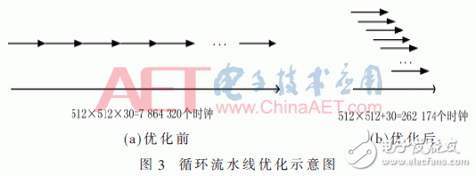
As can be seen from Figure 3, the pixels are processed by the loop, assuming that each pixel processing time is 30 clock cycles. If the processed image size is 512 & TImes; 512, the total number of clocks required before the pipeline optimization is 7 864 320 clock cycles; after the pipeline is optimized, the total number of clocks required is 262 174 clock cycles, and performance has improved by nearly 30 times.
2.3.3 Parallel processing
The SDSoC environment provides async and wait instructions that allow the programmer to control how the hardware functions are synchronized. After the hardware starts working, the async command on the PS side will return the control of the CPU, continue to perform the task of the PS side, and realize the parallel processing of the software and hardware functions. In this way, the parallelism of the system can be increased and the efficiency of the algorithm can be improved. The wait command is used to synchronize data so that the next function can successfully apply the output of a previous hardware function to prevent program deadlock.
3 Analysis of experimental resultsIn this paper, the single-channel .bmp format file is input as the image to be processed, and the template size is selected as 3&TImes; 3. The guided image and the image to be processed are the same image. The experimental effect is shown in Figure 4.
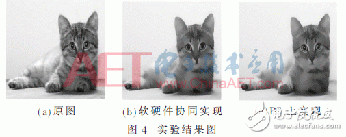
4(a) is the image to be processed and the guidance image, FIG. 4(b) is the guidance filtering effect achieved by the software and hardware co-accelerator, and FIG. 4(c) is the guidance implemented by the OpenCV library software on the PC. Filter effect diagram. It can be seen from the comparison that the boot filter implemented by the software and hardware co-accelerator and the boot filter implemented by the software on the PC are basically the same in effect.
In order to compare the acceleration effect of the hardware and software co-accelerator proposed in this paper, the frame rate value of the boot-filtering algorithm for different size images on the PS side and the frequency value of the boot-filtering algorithm implemented by the software and hardware co-accelerator for different size images are measured. The experimental data is shown in Table 1.

This paper implements the software and hardware co-accelerator for boot filtering, and optimizes the hardware performance by using the optimization instructions provided by the development environment SDSoC. Compared with the boot filter implemented by CUDA, the performance is not as good as it is, but the acceleration effect is obvious, and the advantage in low power consumption and development cycle is greater than CUDA. The software and hardware co-accelerator proposed in this paper can be directly used in embedded systems with built-in CPU and FPGA, which shortens the development cycle of embedded engineers and improves the overall performance of the system.
Small Vacuum Cleaner,Cordless Vacuum Cleaner,Handheld Vacuum Cleaner,Portable Vacuum Cleaner
Ningbo ATAP Electric Appliance Co.,Ltd , https://www.atap-airfryer.com