The parameter tuning of the PID controller is the core content of the control system design. It determines the scale factor, integration time and derivative time of the PID controller according to the characteristics of the controlled process. There are many methods for PID controller parameter tuning. There are two general categories:
Theoretical calculation tuning method
It is mainly based on the mathematical model of the system, and the controller parameters are determined through theoretical calculations. The calculation data obtained by this method may not be directly usable, and must be adjusted and modified through engineering practice.
2. Engineering setting method
It relies mainly on engineering experience and is directly carried out in the test of the control system. The method is simple and easy to master, and is widely used in engineering practice. The engineering tuning method of PID controller parameters mainly includes critical ratio method, reaction curve method and attenuation method. Each of the three methods has its own characteristics, and the common point is to pass the test, and then adjust the controller parameters according to the engineering experience formula. However, no matter which method is used, the controller parameters need to be adjusted and improved in actual operation. The critical ratio method is generally used now. The tuning steps of the PID controller parameters using this method are as follows:
(1) First pre-select a sampling period that is short enough for the system to work;
(2) Add only the proportional control link until the system has a critical oscillation in the step response of the input, and record the proportional amplification factor and the critical oscillation period at this time;
(3) Calculate the parameters of the PID controller by a formula under a certain degree of control.
General principles of PID debugging
a. Increase the proportional gain P when the output does not oscillate.
b. When the output does not oscillate, reduce the integral time constant Ti.
c. Increase the differential time constant Td when the output does not oscillate.
PID debugging general steps
a. Determine the proportional gain P
When determining the proportional gain P, first remove the integral term and the derivative term of the PID, generally let Ti=0, Td=0 (see the parameter setting description of PID for details), so that the PID is pure proportional adjustment. The input is set to 60%~70% of the maximum allowed by the system, and the proportional gain P is gradually increased by 0 until the system oscillates; in turn, the proportional gain P from this time gradually decreases until the system oscillation disappears, recording At this time, the proportional gain P sets the proportional gain P of the PID to 60% to 70% of the current value. Proportional gain P debugging is completed.
b. Determine the integral time constant Ti
After the proportional gain P is determined, the initial value of a larger integral time constant Ti is set, and then Ti is gradually decreased until the system oscillates, and then, in turn, Ti is gradually increased until the system oscillation disappears. Record Ti at this time, and set the integration time constant Ti of the PID to 150% to 180% of the current value. The integration time constant Ti is completed.
c. Determine the integration time constant Td
The integral time constant Td is generally not required to be set and is 0. To set, as in the method of determining P and Ti, take 30% of the oscillation.
d. The system is unloaded and loaded, and the PID parameters are fine-tuned until the requirements are met.
The basic idea of ​​variable speed integral is to try to change the accumulated acceleration of the integral term so that it corresponds to the deviation: the larger the deviation, the slower the integral; the faster the reverse, the better the system quality.
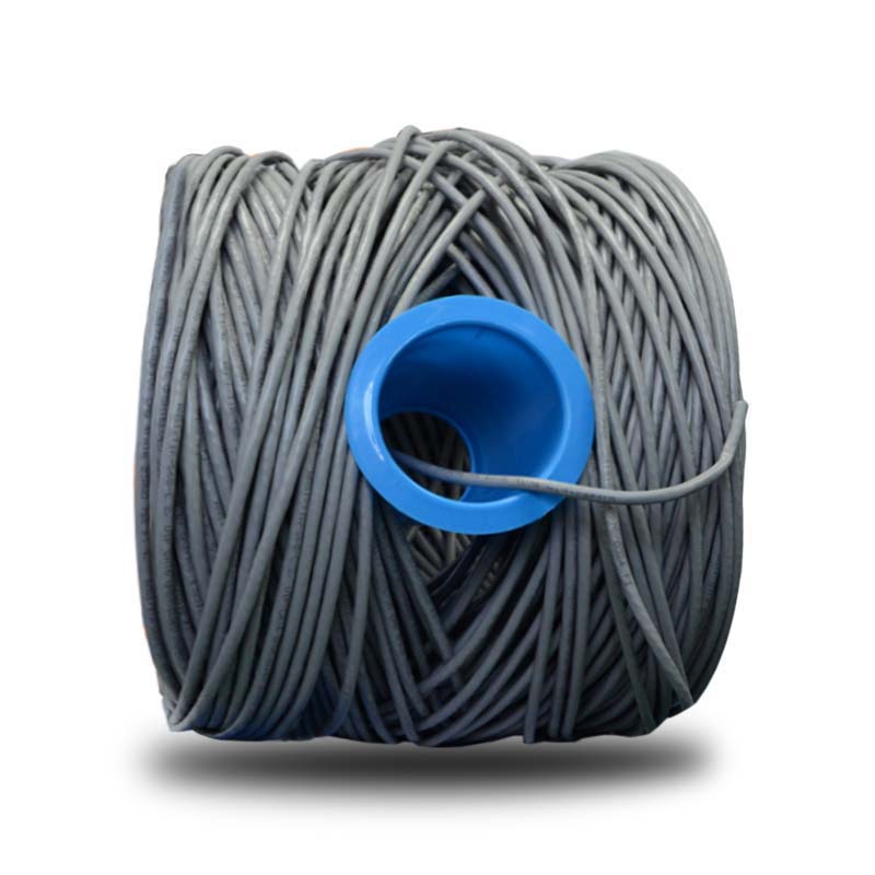
CAT5E Lan Cable are usually 1000ft is created equal, but most engineers agree the small, time saving details make all the difference – like rolling cable out of the box smoothly without snags, durability, reduced cross-talk and of course fulfilling its promise of being a high performance Ethernet Cable.
100% CERTIFIED SOLID BARE COPPER CONDUCTOR: It`s time to forget Copper Clad Aluminum cables (CCA) – With a higher conductivity and tensile strength. 24AWG Solid Copper Conductors transmit faster while lasting the distance. For heavy traffic networks, and as a solid gaming ethernet cable – it`s the type of cat5e cable that just makes perfect sense.

Cat5E Lan Cable,Fiber Optic Ethernet Cable,Ethernet Cable Cat5E,Flat Cat5E Ethernet Cable
Shenzhen Kingwire Electronics Co., Ltd. , https://www.kingwires.com