The PPI protocol is a communication protocol developed specifically for the S7-200. The communication ports (Port 0, Port 1) of the S7-200 CPU support the PPI communication protocol. The PPI network communication of the S7-200 CPU is based on the hardware of the RS-485 network, so the connection properties and required network hardware devices are consistent with other RS-485 networks.
Network read and write instructions are generally used for PPI network communication between S7-200 CPUs. Before PPI communication, ensure that all sites on the PPI network should have different network addresses, otherwise the communication will not proceed normally. In addition, the following points should be noted when programming and applying network read/write instructions:
1) Any network read/write instruction can be used in the program, but at the same time, only 8 network read/write instructions can be activated at most.
2) Each network read and write instruction can read/write up to 16 bytes of information from the remote site;
3) Use the NETR/NETW command wizard to edit up to 24 network read and write instructions, the core of which is to use sequential control instructions so that only one NETR/NETW instruction is valid at any one time;
4) Only one network read/write instruction wizard can be configured for each CPU port.
The following example shows how to use the Network Read and Write Command Wizard with an example (communication between two S7-200 plcs). First, the hardware connection between the two S7-200s requires a standard DP cable plus two DP bus plugs. For the RS485 communication port connection mode of two S7-200s, refer to the connection mode in the following picture (if the PLC has two communication ports, any port can be configured. In this example, both PLCs use Port 0 as the PPI. Communication is used), as shown in Figure 1.
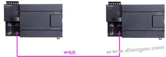
Figure 1 Network connection of two PLCs
First, set the network address of the two PLCs to 2 and 3 with the PC/PPI programming cable, and the baud rate is 9.6Kbps. At this time, connect the programming cable to any DP plug with a programmable socket to find the station address of the two PLCs, as shown in Figure 2.
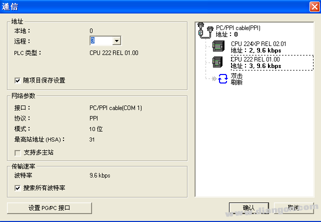
Figure 2 Setting the network address of two CPUs
In this example, the PLC with the communication address of 3 is selected as the network master and wizard configuration is performed. Select the CPU address to be the communication master station, click OK to enter the programming interface of the CPU. In addition, the network read/write command wizard will automatically set the CPU to the master mode. It does not need to be programmed separately. It only needs to write the communication program for the master station. The slave directly uses the data in the communication buffer or organizes the data into the communication area. can.
After entering the programming screen, click on the tool menu bar to find the command wizard option, ready to enter the network read/write function wizard configuration mode, as shown in Figure 3.
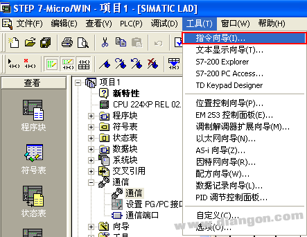
Figure 3 enters the command wizard programming interface
Open the command wizard interface and select the NETR/NETW command function, as shown in Figure 4.
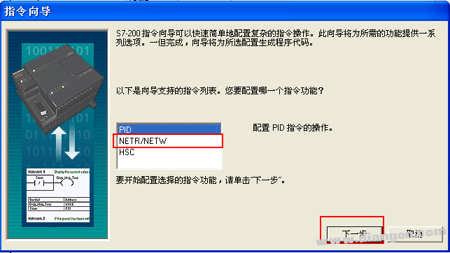
Figure 4 NETR / NETW command wizard interface
After selecting the network read and write command, click Next to define the number of network operations required for communication, as shown in Figure 5. Up to 24 network read and write operations can be used in the wizard. For more operations, network read and write instructions can be used to program. In this example, two network operations will be established.
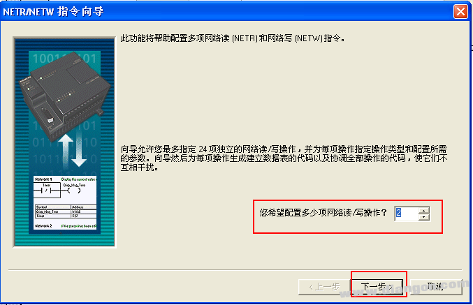
Figure 5 Determination of the number of network read and write operations
Next, select the serial number of the PLC port to be used for the communication master station. Here, select the PORT 0 port as the communication master station port, and name the wizard configuration subroutine to be generated (you can use the default name or self-name). For a CPU with two communication ports, you can select either Port 0 or Port 1, and all network operations will be done by the defined communication port, as shown in Figure 6.
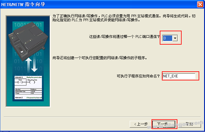
Figure 6 defines the network port number and names the subroutine name
Click Next to enter the setting interface of the data exchange area, as shown in Figure 7.
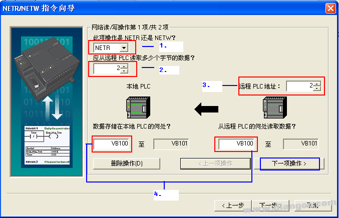
Figure 7 Network read data exchange configuration interface
among them:
1. The delegate defines whether the network operation is a network read (NETR) or a network write (NETW) operation;
2. The delegate defines how many data bytes (NETR) should be read from the remote PLC or how many data bytes (NETW) should be written to the remote PLC. Each network read and write instruction can send or receive up to 16 bytes of data. ;
3. The delegate defines the remote PLC address that you want to communicate with;
4. When the delegate defines a network read (NETR) or network write (NETW) operation, define which address area of ​​the local PLC the data to be read or written should exist, and the data to be written and read is defined in Which address area in the remote PLC, the valid operands are VB, IB, QB, MB, LB;
Because two network read/write operations have been defined before, another network read/write operation instruction can be configured in the “next operationâ€. The configuration content is similar to the above interface, and will not be repeated. Defined as a network read operation in the first operation, the address assignment is as shown in Figure 7; the next operation will be defined as a network write (NETW) operation, and the specific address assignment is as shown in Figure 8.
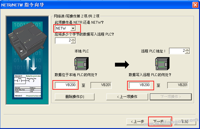
Figure 8 Configuration screen of network write operation
Finally, you need to allocate the recommended address of the V memory area. It is recommended to set the V memory area start address to be larger (as shown in Figure 9). The principle is to avoid overlapping with the V memory area address already applied in the program.
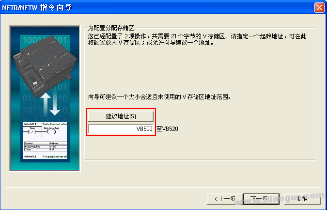
Figure 9 suggests address area allocation
After completing the above steps, the wizard's configuration process is completed. After the wizard configuration is completed, the subroutine and symbol table of the network read/write instructions are automatically generated.
After completing the wizard configuration, enter the block programming. The content of the programming is to call the subroutine generated by the wizard, and finally download the program to the corresponding PLC to make it effective, as shown in Figure 10.

Figure 10 Calling the wizard generated subroutine module
among them:
1) NETR/NETW must be enabled with SM0.0 to ensure the normal operation of the instruction;
2) Timeout: timeout parameter. 0 = no delay; 1-32767 = indicates the timeout delay in seconds. If the time in which the communication has a problem exceeds the delay time, an error is reported;
3) Cycle: Cycle parameter. This parameter switches its switch state every time all network read and write operations are completed;
4) Error: Error parameter. 0 = no error, 1 = error.
First, open the status table of the main station CPU 222, input the exchange address area of ​​the data, and assign the value in the VB200~VB201 area of ​​the NETW instruction, then select the slave CPU 224XP in the communication interface, and open its status table for monitoring. Check whether its VB200 and VB201 have value writes, and write new values ​​in VB100 and VB101, and then open the status table of the master CPU 222 to monitor whether the corresponding address area receives the value, thus completing as shown in FIG. Read/write data exchange process.
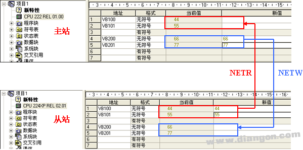
Figure 11 Master/slave communication data exchange
If the data area does not receive data, then the communication is unsuccessful and the status byte of the communication needs to be viewed to obtain the error code. The status byte of each read/write operation can be referred to the NET_SYMS tab field generated in the symbol table after the instruction wizard is successfully configured, as shown in FIG. The V area address corresponding to the status byte is as shown in Figure 13 (the status byte address will be different depending on the starting address of the allocated V memory area), for example, the status byte address corresponding to the first NETR operation. For VB503.
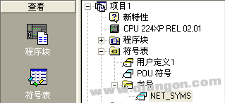
Figure 12 NET_SYMS generated in the symbol table

Figure 13 Communication read/write instruction status byte
The specific meaning of each bit in the status byte is as shown in the red box in Figure 14.
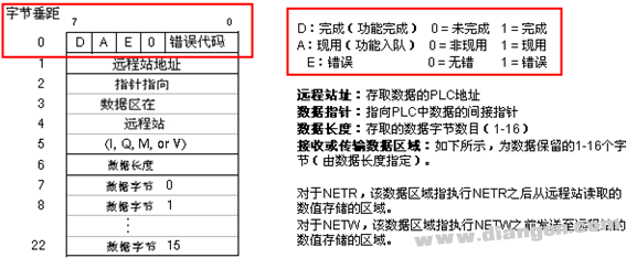
Figure 14 Status byte meaning
It can be seen from the above figure that the error code only occupies the lower 4 bits of the status byte. Converting it to a decimal value represents the error code. The specific description of the error code is shown in Figure 15.
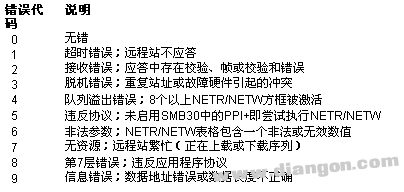
Figure 15 Communication error code description
Corner light ,led Corner light ,Waterproof Corner Light,Bright LED corner light
Kindwin Technology (H.K.) Limited , https://www.ktl-led.com